Retired Document
Important: This document may not represent best practices for current development. Links to downloads and other resources may no longer be valid.
Expansion Features
This chapter describes the expansion features of the 17-inch PowerBook G4’s RAM expansion slots and the PC Card/CardBus slot.
RAM Expansion Slots
The 17-inch PowerBook G4 ships with 512 MB of factory-installed SDRAM. The computer has two RAM expansion slots that accommodate standard SO (small outline) DIMMs using PC2-4200 DDR2 SDRAM devices. The expansion slots are accessible for user installation of an additional SO-DIMM. Available as build to order options are 512 MB and 1 GB RAM.
The address logic for the RAM slots supports up to 2 GB total RAM. Using the highest-density devices currently available, an SO-DIMM can contain up to 1 GB of RAM, so the two RAM expansion slots can accommodate up to 2 GB total RAM.
Accessing the RAM Slots
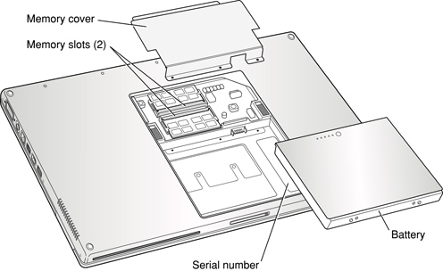
The user can access the RAM expansion slots by removing the memory slot cover on the back of the computer, as shown in Figure 4-1. For complete instructions on accessing and replacing the RAM memory, refer to the 17-inch PowerBook G4 Getting Started guide that came with the computer.
Mechanical Design of DDR2 RAM SO-DIMMs
The RAM expansion modules used in the 17-inch PowerBook G4 are PC2-4200 DDR2 SDRAM SO-DIMMs, as defined in the JEDEC specifications. The SO-DIMM runs at 333 MHz.
The mechanical characteristics of the RAM expansion SO-DIMM are given in the JEDEC specification for the DDR2 SO-DIMM. The specification number is JEDEC JESD95. To obtain a copy of the specification, see the references listed at RAM Expansion Modules.
The specification defines SO-DIMMs with nominal heights of 1.0, 1.25, 1.5, and 2.0 inches. The 17-inch PowerBook G4 can accommodate SO-DIMMS with heights of 1.25 inches or less.
The JEDEC specification defines the maximum depth or thickness of an SO-DIMM as 3.8 mm. Modules that exceed the specified thickness can cause reliability problems.
Electrical Design of DDR2 RAM SO-DIMMs
SO-DIMMs for the 17-inch PowerBook G4 are required to be PC2-4200 compliant. For information about the PC2-4200 specifications, see the references at RAM Expansion Modules.
The electrical characteristics of the DDR2 RAM SO-DIMM are given in the JEDEC specification. To obtain a copy of the specification, see the references listed at RAM Expansion Modules.
The JEDEC and Intel specifications define several attributes of the DIMM, including storage capacity and configuration, connector pin assignments, and electrical loading. The specifications support SO-DIMMs with either one or two banks of memory.
The JEDEC specification for the SO-DIMM defines a Serial Presence Detect (SPD) feature that contains the attributes of the module. SO-DIMMs for use in PowerBook computers are required to have the SPD feature.
Capacitance of the data lines must be kept to a minimum. Individual DRAM devices should have a pin capacitance of not more than 5 pF on each data pin.
DDR2 SDRAM Devices
The DDR2 SDRAM devices used in the RAM expansion modules must be self-refresh type devices for operation from a 2.5 V power supply. The data rate of the DDR2 SDRAM devices must be 333 MHz.
The devices are programmed to operate with a CAS latency of 3 or 4. At these CAS latencies, the access time from the clock transition must be +/- 0.6 ns or less for data strobes and +/- 0.7 ns for data lines. The burst length must be at least 4 and the minimum clock delay for back-to-back random column access cycles must be a latency of 1 clock cycle.
When the computer is in sleep mode, the RAM modules are in self-refresh mode and the maximum power-supply current available for each RAM module is 6 mA/128 MB (48 mA per RAM module); see the section RAM SO-DIMM Electrical Limits . Developers should specify DDR2 SDRAM devices with low power specifications so as to stay within that limit.
Configuration of DDR2 RAM SO-DIMMs
Table 4-1 shows information about the different sizes of DDR2 SDRAM devices used in the memory modules.
DIMM size | Device size | Device Configuration (depth x bits x banks) | Devices per rank | Rank size | # of ranks |
|---|---|---|---|---|---|
256 MB | 256 Mbits | 8 M x 8 x 4 | 8 | 256 MB | 1 |
512 MB | 256 Mbits | 8 M x 8 x 4 | 8 | 256 MB | 2 |
512 MB | 512 Mbits | 8 M x 16 x 4 | 4 | 512 MB | 1 |
512 MB | 512 Mbits | 16 M x 8 x 4 | 8 | 512 MB | 1 |
1 GB | 512 Mbits | 8 M x 16 x 4 | 4 | 512 MB | 2 |
1 GB | 512 Mbits | 16 M x 8 x 4 | 8 | 512 MB | 2 |
1 GB | 1 Gbits | 8 M x 16 x 8 | 4 | 1 GB | 1 |
1 GB | 1 Gbits | 16 M x 8 x 8 | 8 | 1 GB | 1 |
Address Multiplexing
Table 4-2 lists the types of devices that can be used in the 17-inch PowerBook G4.
Device size | Device configuration (depth x bits x banks) | Row address bits | Column address bits | Bank address |
|---|---|---|---|---|
256 Mbits | 8 M x 8 x 4 | 13 | 10 | BA[0-1] |
512 Mbits | 8 M x 16 x 4 | 13 | 10 | BA[0-1] |
512 Mbits | 16 M x 8x 4 | 14 | 10 | BA[0-1] |
1 Gbits | 8 M x 16 x 8 | 13 | 10 | BA[0-2] |
1 Gbits | 16 M x 8x 8 | 14 | 10 | BA[0-2] |
RAM SO-DIMM Electrical Limits
Each RAM SO-DIMM must not exceed the following maximum current limits on the 1.8 V supply:
Active: 1.2 A (8 devices at 150 mA each)
Sleep: 6 mA/128 MB (48 mA per RAM module)
The Intrepid memory controller does not support 4-bit-wide SDRAM devices in any RAM expansion module.
PC Card/CardBus Slot
The PC Card/CardBus slot accepts one Type I or Type II card. The slot supports both 16-bit PC Cards and 32-bit CardBus Cards. The card can be removed and replaced while the computer is operating.
Copyright © 2003, 2005 Apple Computer, Inc. All Rights Reserved. Terms of Use | Privacy Policy | Updated: 2005-10-19