Retired Document
Important: This document may not represent best practices for current development. Links to downloads and other resources may no longer be valid.
Devices and Ports
This chapter describes both the built-in I/O devices and the ports for connecting external I/O devices. Each of the following sections describes an I/O port or device.
USB Ports
The iBook computer has two Universal Serial Bus (USB) ports that can be used to connect additional I/O devices such as a USB mouse, printers, scanners, and low-speed storage devices. The USB ports are located on the left side of the computer.
For more information about USB on Macintosh computers, please refer to Apple Computer’s Mac OS USB DDK API Reference and the other sources listed in USB Interface.
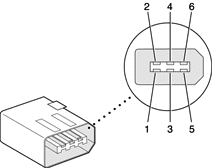
USB Connector
The USB port uses a USB Type A connector, which has four pins. Two of the pins are used for power and two for data. Figure 3-1 is an illustration of a Type A USB port. Table 3-1 shows the pin assignments.

Pin | Signal name | Description |
|---|---|---|
1 | VCC | +5 VDC |
2 | D– | Data – |
3 | D+ | Data + |
4 | GND | Ground |
The iBook computer provides power for the USB ports at 5 V and up to 500 mA each.
Each USB port supports both low-speed and high-speed data transfers, at up to 1.5 Mbps and 12 Mbps, respectively. High-speed operation requires the use of shielded cables.
The Macintosh USB system software that comes with the iBook computer supports all four data transfer types defined in the USB specification.
USB Technology
The USB ports include power saving modes, support of USB mass-storage devices, and an OHCI controller.
Wake on Connect and Resume
The Pangea IC contains special circuitry that allows the computer to wake from Sleep mode on connect, disconnect, and resume events. Compatible USB devices should support the USB-suspend mode defined in the USB specification. Information about the operation of USB-suspend mode on Macintosh computers is included in the Mac OS USB DDK API Reference.
USB Storage Devices
Class drivers are software components that are able to communicate with many USB devices of a particular kind. If the appropriate class driver is present, any number of compliant devices can be plugged in and start working immediately without the need to install additional software. The Mac OS for the iBook computer includes USB Mass Storage Support 1.3, a class driver that supports devices that meet the USB Mass Storage Class specification. For information about USB support on the Macintosh, see the references in USB Interface.
USB Controller
The iBook computer uses an Open Host Controller Interface (OHCI) controller for USB communication. Some early USB devices (most notably keyboards) can’t interoperate with an OHCI controller. Those devices are not supported by the Macintosh USB system software.
FireWire 400 Port
The iBook computer has one external FireWire 400 IEEE 1394a port. The FireWire 400 port
supports serial I/O at 100, 200, and 400 Mbps (megabits per second)
provides up to 7 watts of peak power when the computer system is on or the power adapter is connected.
supports booting the system from a mass storage device
supports target disk mode (TDM)
The FireWire 400 hardware and software provided with the iBook computer are capable of all asynchronous and isochronous transfers defined by IEEE standard 1394.
FireWire 400 Connector
The FireWire 400 connector has six contacts, as shown in Figure 3-2. The connector pin assignments are shown in Table 3-2.
When the computer is on or the power adapter is connected, the power pin provides a maximum voltage of 16.8 V (no load) and up to 7 W peak power.
Pin 2 of the 6-pin FireWire 400 connector is ground for both power and the inner cable shield. If a 4-pin connector is used on the other end of the FireWire 400 cable, its shell should be connected to the wire from pin 2.
The signal pairs are crossed in the cable itself so that pins 5 and 6 at one end of the cable connect with pins 3 and 4 at the other end. When transmitting, pins 3 and 4 carry data and pins 5 and 6 carry clock; when receiving, the reverse is true.
FireWire 400 Device Programming
A generic driver for mass storage devices is included in the system software. This driver is used only when a vendor-specific driver cannot be found. Apple recommends that users install vendor-provided drivers for maximum performance and functionality.
A driver for DV (digital video) is included in QuickTime 4.0 and later versions.
The iBook computer can boot from a FireWire 400 storage device that implements SBP-2 (Serial Bus Protocol) with the RBC (reduced block commands) command set. Detailed information is available only under non-disclosure agreement; contact Developer Technical Support at dts@apple.com.
When connected to another computer by a FireWire 400 bus, the iBook computer can operate as a mass storage device. See Target Disk Mode.
For additional information about the FireWire 400 interface and the Apple APIs for FireWire 400 device control, refer to the resources listed in FireWire 400 Interface.
Ethernet Port
The iBook computer has a built-in 10/100 Mbps Ethernet port. The user can connect it to either a 10Base-T or a 100Base-T hub; the port will automatically sense which type of hub is connected.
The connector for the Ethernet port is a shielded RJ-45 connector near the left rear corner of the computer. Table 3-3 shows the signals and pins on the connector.
When connecting two computers using Ethernet, a crossover cable is not required; circuits in the PHY detect the type of connection and switch the signal configuration as required.
The Ethernet interface in the iBook computer conforms to the ISO/IEC 802.3 specification, where applicable.
Internal Modem
The iBook computer comes with a built-in modem.The connector for the modem is an RJ-11 connector on the left rear corner of the computer.
The modem has the following features:
modem bit rates up to 56 Kbps (V.92 modem standards)
fax modem bit rates up to 14.4 Kbps
The modem appears to the system as a serial port that responds to the typical AT commands. The modem provides digital sound output data to the Pangea IC for monitoring the progress of the modem connection.
AirPort Card
The iBook computer supports the AirPort Card, an internal wireless LAN module. The AirPort Card is available as a build-to-order option or as a user-installable upgrade through The Apple Store.
By communicating wirelessly with a base station, the AirPort Card can be used for internet access, email access, and file exchange. A base station provides the connection to the internet or the bridge between the wireless signals and a wired LAN or both. The AirPort Base Station and AirPort Extreme Base Station have connectors for a wired LAN, a DSL or cable modem, and a standard telephone line using using the built-in 56 Kbps modem that is available on some base stations.
AirPort transmits and receives data at speeds up to 11 Mbps, comparable to wired networking speeds. Airport is Wi-Fi Certified, which means it is fully compatible with other devices that follow the IEEE 802.11b standard, including PC's. For more information about Wi-Fi and compatibility, see the reference at Wireless Networks.
Data Security
AirPort has several features designed to maintain the security of the user’s data.
The system uses direct-sequence spread-spectrum (DSSS) technology that uses a multi-bit spreading code that effectively scrambles the data for any receiver that lacks the corresponding code.
The system can use an Access Control List of authentic network client ID values (wireless and MAC Addresses) to verify each client’s identity before granting access to the network.
When communicating with a base station, AirPort uses up to 128-bit encryption to encode data while it is in transit.
The AirPort Base Station can be configured to use NAT (Network Address Translation), protecting data from would-be Internet hackers.
The AirPort Base Station can authenticate users by their unique Ethernet IDs, preventing unauthorized machines from logging into the network. Network administrators can take advantage of RADIUS compatibility, used for authenticating users over a remote server. Smaller networks can offer the same security using a local look-up table located within the base station.
AirPort Hardware
The AirPort Card is a wireless LAN module based on the IEEE 802.11 standard and using direct-sequence spread-spectrum (DSSS) technology. It is interoperable with PC-compatible wireless LANs that conform to the 802.11b standard and use DSSS.
Two AirPort antennas are built into the computer’s cover, on either side of the flat-panel display. One antenna is always used for transmitting. Either of the two antennas may be used for receiving. Using a diversity technique, the AirPort Card selects the antenna that gives the best reception.
AirPort Software
Software that is provided with the AirPort Card includes
AirPort Setup Assistant, an easy-to-use program that guides users through the steps necessary to set up the AirPort Card or set up an AirPort Base Station.
Users can switch between wireless networks and can create and join peer-to-peer networks. In Mac OS X, these functions are accessed via System Preferences or the AirPort status menu (which first must be activated in System Preferences). In Mac OS 9, these functions are available through the AirPort application and the menu bar.
AirPort Admin Utility, a utility for advanced users and system administrators. With it the user can edit the administrative and advanced settings needed for some advanced configurations.
Bluetooth Technology
In the iBook computer, the Bluetooth option requires an external, third-party dongle connected via the USB bus. Bluetooth is an open specification that enables short-range wireless connections between desktop and laptop computers and a host of other peripheral devices. Bluetooth support is built into Mac OS X and compliant with Bluetooth specification v1.1. It operates on a globally available 2.4 GHz frequency band (ISM band) for worldwide compatibility and has a maximum throughput of 1Mbps.
The Bluetooth technology supports the following profiles:
synchronization —enables synchronization of devices over Bluetooth
serial —provides a wireless serial connection to other Bluetooth devices
dial-up networking (DUN) — enables a mobile phone to act as a modem
object push —enables the transfer of files between Bluetooth devices
For more information on Bluetooth technology, refer to Bluetooth.
Hard Disk Drive
The storage capacity of the internal hard disk drive is 30 GB on the CD-ROM model and 40 GB on models with Combo drive. A 60 GB drive is available as an option. The drive uses the Ultra DMA IDE (integrated drive electronics) interface and is ATA-5 compatible. Current Data Transfer Mode for the drive is UDMA-33.
The software that supports the internal hard disk is similar to that in previous models with internal IDE drives and includes DMA support. For the information about that software, see the references in ATA Devices.
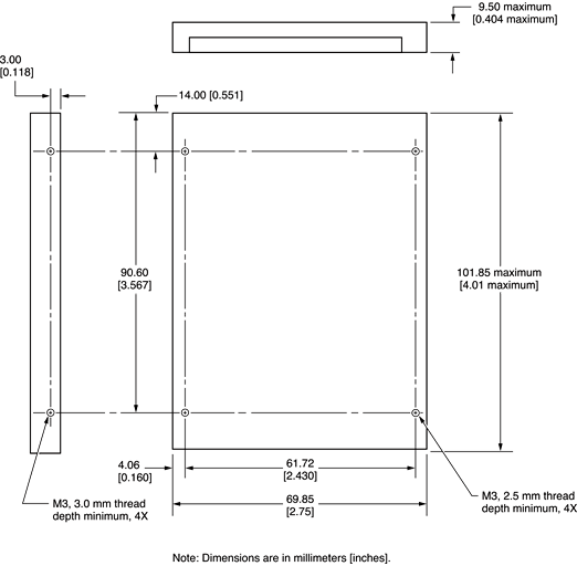
Hard Disk Dimensions
Figure 3-3 shows the maximum dimensions of the hard disk and the location of the mounting holes. The minimum clearance between any conductive components on the drive and the bottom of the mounting envelope is 0.5 mm.
Hard Disk Connector
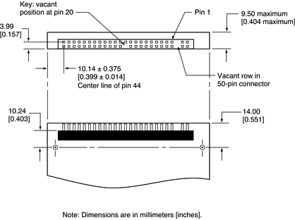
The internal hard disk has a 48-pin connector that carries both the ATA signals and the power for the drive. The connector has the dimensions of a 50-pin connector, but with one row of pins removed, as shown in Figure 3-4. The remaining pins are in two groups: pins 1–44, which carry the signals and power, and pins 45–48, which are reserved. Pin 20 has been removed, and pin 1 is located nearest the gap, rather than at the end of the connector.
Signal Assignments
Table 3-4 shows the signal assignments on the 44-pin portion of the hard disk connector. A slash (/) at the beginning of a signal name indicates an active-low signal.
ATA Signal Descriptions
Table 3-5 describes the signals on the ATA hard disk connector.
The built-in ATA devices are connected to the I/O bus through bidirectional bus buffers.
DVD-ROM/CD-RW Combo Drive
The computer has a combination DVD-ROM and CD-RW drive. The drive has a tray for loading the disc.
The drive can read DVD media and read and write CD media, as shown in Table 3-6. The DVD-ROM/CD-RW Combo drive also provides DVD-Video playback with DVD MPEG2 decode.
Digital audio signals from the DVD-ROM/CD-RW Combo drive can be played through the sound outputs under the control of the Sound Manager.
CD-ROM Drive
One configuration of the iBook computer has an internal CD-ROM drive. The drive has a tray for loading the disc. The drive supports a maximum 24X data transfer rates using constant angular velocity (CAV) and a data buffer, and writes to constant linear velocity (CLV).
The CD-ROM drive supports the worldwide standards and specifications for CD-ROM and CD-digital audio discs described in the Sony/Philips Yellow Book and Red Book. The drive can read CD-ROM, CD-ROM XA, CD-I, PhotoCD, and Video CD discs as well as play standard audio discs.
Digital audio signals from the CD-ROM can be played through the sound outputs under the control of the Sound Manager.
Trackpad
The pointing device in iBook computer is a trackpad. The trackpad is a solid-state device that emulates a mouse by sensing the motions of the user’s finger over its surface and translating those motions into digital signals.
A single button below the trackpad is used to make selections. Alternatively, the user can tap and double tap on the pad itself, depending on the trackpad settings in System Preferences. As described in the user’s manual, the trackpad responds to one or two taps on the pad itself as one or two clicks of the button. The user can tap and drag on the trackpad in much the same manner as clicking and dragging with the mouse.
Keyboard
The keyboard is a compact, low-profile design with a row of function keys and inverted-T cursor motion keys.
Removing the Keyboard
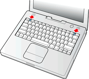
The keyboard is removable to allow access to the internal components and expansion connectors inside the computer. The keyboard is held in place by a locking screw and two latches.
To unlock the keyboard, the user turns a slotted screw that is part of the Num Lock LED, which is between the F5 and F6 function keys. Turning the screw 180 locks or unlocks the keyboard.
The two latches are between the ESC key and the F1 key and between the F11 and F12 keys. The user can release the latches by pulling them toward the front of the computer; see Figure 3-5.
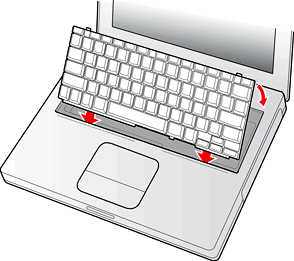
Getting access to the AirPort Card and memory card in the RAM expansion slot takes further steps. For a full description, see The RAM Expansion Slot.
Keyboard Illustrations
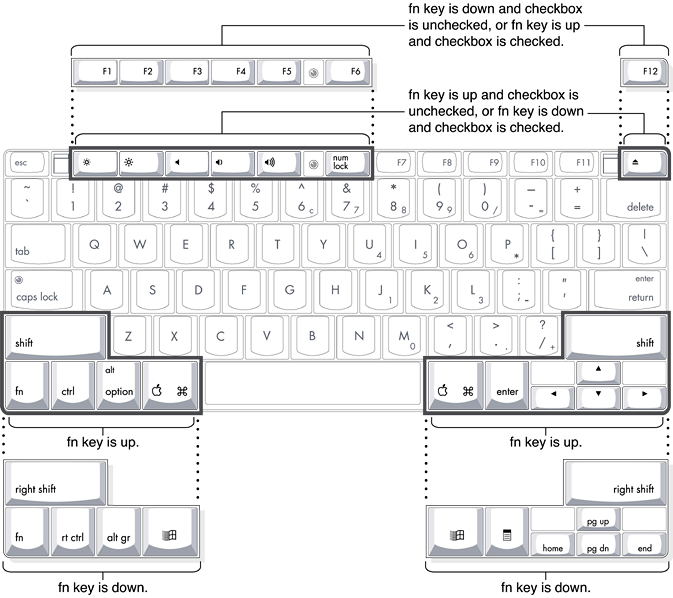
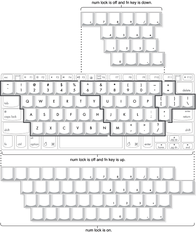
Figure 3-7 shows the appearance of the keyboard. Figure 3-8 shows the alternate modes of operation of the function and control keys. Figure 3-9 shows the embedded numeric keypad.
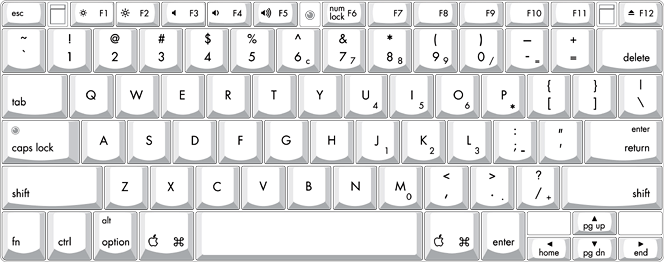
Figure 3-8 and Figure 3-9 include duplicate versions of some keys in order to show their alternate modes of operation. In some cases, the alternate key captions shown in the figures do not appear on the keyboard. For the basic appearance of the keyboard, refer to Figure 3-7.
Changing the Operation of the Keyboard
Several of the keys on the keyboard have more than one mode of operation.
Function keys F1–F6 can also control the display brightness, speaker volume, and the Num Lock function; function key F12 is also the media eject key.
Certain control keys can be used as page-control keys.
The keys on the right side of the keyboard can be used as a numeric keypad.
The next sections describe these groups of keys and the way their alternate modes of operation are selected by using the Fn key, the Num Lock key, and the Function Keys checkbox in the Keyboard control panel.
Using the Fn Key
Pressing the Fn key affects three sets of keys: the function keys F1–F12, the embedded numeric keypad, and certain modifier keys.
It toggles the function keys between their control-button operation and their F1–F12 functions, as shown in Table 3-8 and Figure 3-8. In Mac OS 9, the user selects the default modes of operation of those keys as described in the section The Function-Keys Checkbox.
It selects the embedded numeric keypad on the right portion of the alphanumeric keys, as shown in Table 3-9 and Figure 3-9.
It changes certain control keys, including the cursor control keys, to page control keys, as shown in Table 3-10 and Figure 3-9.
Using the Num Lock Key
Pressing the Num Lock key affects two sets of keys: the embedded keypad and the rest of the alphanumeric keys.
It selects the embedded numeric keypad, as shown in Table 3-9 and Figure 3-9.
It makes the rest of the alphanumeric keys functionless (NOPs), as shown in Figure 3-9.
The Function-Keys Checkbox
The Function-keys checkbox is supported in Mac OS 9. The Fn key lets the user switch the mode of operation of the function keys at any time. The user selects the default mode of the function keys by means of the Function-keys checkbox in the Keyboard Control Panel.
The Function-keys checkbox lets the user choose whether the function key operations are primary or secondary. “Function keys primary” means the function keys are normally in their F1–F12 mode of operation and pressing the Fn key selects their control-button mode. “Function keys secondary” means the function keys are normally in their control-button mode and pressing the Fn key selects their function-key mode.
In other words, pressing the Fn key reverses the mode of operation of the function keys from the default mode set by the checkbox. Table 3-7 summarizes the checkbox settings and the operation of the Fn key. The operations of the individual function keys are shown in Table 3-8 and Figure 3-8.
Operations of the Function Keys
Function keys F1 through F6 are used as control buttons for the display and sound and F12 is used for media eject (hold down F12 button for one or 2 seconds). The operations of the function keys are controlled by the Function keys checkbox and the Fn key. Table 3-8 is a list of the function keys and their operations as control buttons.
The Embedded Keypad
A certain group of alphanumeric keys can also function as an embedded keypad. The user selects this mode by using the Fn key or the Num Lock key. Figure 3-9 shows the keys making up the embedded keypad and Table 3-9 lists them.
Key name | Keypad function |
|---|---|
6 | Clear |
7 | 7 |
8 | 8 |
9 | 9 |
0 | / (divide) |
- | = (equals) |
U | 4 |
I | 5 |
O | 6 |
P | * (multiply) |
J | 1 |
K | 2 |
L | 3 |
; | – (subtract) |
M | 0 |
, | NOP |
. | . (decimal) |
/ | + (add) |
When the embedded keypad is made active by the Num Lock key, the other alphanumeric keys have no operation (NOP), as shown in Figure 3-9. The affected keys include certain special character keys: plus and equal sign, right and left brackets, vertical bar and backslash, and straight apostrophe.
Other Control Keys
The cursor control keys can also be used as page control keys. Other control keys can take on the functions of certain keys on a PC keyboard, for use with PC emulation software. The Fn key controls the modes of operation of this group of keys. Table 3-10 is a list of these keys and their alternate functions. These control keys are also show in Figure 3-9.
Flat Panel Display
The iBook computer has a built-in color flat panel display. The display is backlit by a cold cathode fluorescent lamp (CCFL). The display uses TFT (thin-film transistor) technology for high contrast and fast response.
Depending on the model, the display is either 12.1 or 14.1 inches in size, measured diagonally. The display contains 1024 by 768 pixels (XGA) and can show up to millions of colors.
The graphics controller IC is an ATI Mobility Radeon 7500. The graphics IC has 32 MB of video DDR SDRAM on the chip. It supports 3D acceleration and display depths up to 24 bits per pixel. When more graphics storage is needed, the graphics IC can also use part of main memory. For more information, see Graphics IC.
The graphics IC includes a scaling function that expands smaller-sized images to fill the screen. By means of the scaling function, the computer can show full-screen images at 1024 by 768, 800 by 600, or 640 by 480 pixels.
External Display Port
The iBook computer has a video output port for connecting an external video monitor or projector. The port supports both VGA and TV signals by means of adapters. The port detects the type of adapter connected to it and programs the graphics IC to provide the appropriate type of video signals, as shown in the table below.
Adapter type | Video signals | Connector type(s) |
|---|---|---|
VGA | RGB | VGA 15-pin miniature D-type |
Video | Composite and S-video TV signals | RCA and S-video |
Resolutions supported are 640 by 480, 800 by 600, and 1024 by 768 pixels. When either type of display adapter is connected, the settings for the resolutions are selectable in the Monitor control panel or control strip.
Composite video and S-video signals can be displayed on either an NTSC display or a PAL display. When a display is connected by way of the video adapter, the computer detects the type of adapter and enables the composite and S-video outputs. The settings for the resolutions and standards (NTSC or PAL) are then selectable in the monitor control panel or control strip.
The video output mirrors the flat panel display: internal and external video share the same buffer, and the hardware sends the image to both displays.
Video Display Connector
The video display connector is a 14-pin rectangular connector, Hosiden TCX3143, or compatible. The connector pins are identified in Figure 3-10.
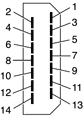
The iBook computer detects the type of display adapter that is plugged in and programs the graphics IC to route the appropriate video signals to the connector. The signal assignments on the video connector are shown in Table 3-12. The signal assignments for the video adapter are shown in Table 3-13.
The cable detect function on pin 13 is implemented by connecting pin 13 to ground in the display cable. The computer detects the video adapter by reading its EDID (Extended Display Identification Data) via DDC.
The video display connector is compliant with the VESA specification (DDC version 3).
Older Monitors Not Supported
The computer supports current video monitors. Some older monitors are not supported, including the following Apple monitors:
Multiple Scan 17
Multiple Scan 20
AudioVision 14
Apple Hi-Res RGB
Apple 16" Color
Apple Hi-Res Monochrome
Macintosh 12" RGB
Sound System
The 16-bit stereo audio circuitry provides sound input through the built-in microphone and the USB port and sound output through the built-in stereo speakers and the audio minijack.
All audio is handled digitally inside the computer, including audio data from the DVD-ROM/CD-RW Combo drive or CD-ROM drive, the modem, and devices connected to the USB and FireWire ports. Sound data is converted to analog form only for output to the internal speakers and the audio minijack.
The sound circuitry handles audio data as 44.1 kHz 16-bit samples. If audio data sampled at a lower rate on another computer is played as output, the Sound Manager transparently upsamples the data to 44.1 kHz prior to sending the audio data to the sound circuitry.
Audio Minijack
The audio minijack is located on the left side of the computer at the left palm rest. The jack accepts a standard stereo mini-plug.
The stereo audio signals at the jack are configured to drive a pair of low-impedance stereo headphones. External powered speakers may also be connected to the audio minijack.
The audio signals on the audio minijack have the following electrical characteristics:
output impedance: 16 ohms each channel
minimum recommended load impedance: 32 ohms each channel
maximum level: 1.0 V rms (2.8 V P-P)
Internal Microphone
The computer has a built-in microphone located at the upper right hand corner of the display.
Internal Speakers
The computer has a stereo pair of speakers located between the keyboard and the display. The sound system provides parametric equalization for the speakers. The computer turns off the sound signal to the speakers when headphones are connected to the audio mini-jack and when USB speakers are active.
Sound effects and output from other audio sources can be specified in the System Preferences Sound panel. An output device is displayed on the Sound panel when the computer detects that it is plugged in. The system default setting is the internal audio controller. Once the default is changed to a different device, it will remain the default as long as the device is plugged in.
Internal Modem
The Pangea IC receives call progress audio from the internal modem as digital data and sends it to the sound system so the user can hear the status of a dial-up modem connection. The level of the call progress audio is fixed.
CD Audio
Digital audio data from the CD or Combo drive is read using the ATA interface, processed by the audio software, and then transferred by DMA through the I2S interface of the Pangea IC to the sound system or sent to USB speakers.
Copyright © 2003 Apple Computer, Inc. All Rights Reserved. Terms of Use | Privacy Policy | Updated: 2003-04-22