Thunderbolt Technology Overview
This chapter describes the basic components and functions of the Thunderbolt technology and how these are used with DisplayPort (DP) and PCI Express (PCIe) devices.
The Beginning: The Thunderbolt Controller Chip
The Thunderbolt interface is a revolutionary I/O technology that supports high-resolution displays and high-performance data devices through a single, compact port. It sets new standards for speed, flexibility, and simplicity. At the core of this technology is the Intel Thunderbolt controller chip.
For example, the first generation of controller chip is the 82524EF controller as shown in Figure 1-1.
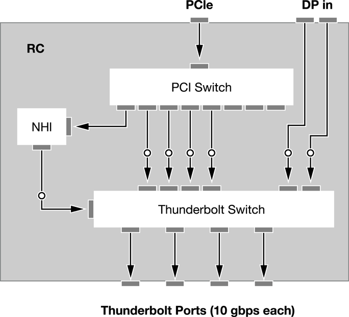
The Intel controller chip can be used in both host mode and endpoint mode. In host mode, the controller has a Gen2 x4 uplink to the system PCI Express Root Complex and one or more DisplayPort (DP) inputs (depending on the graphics capabilities of the system). Additionally, there is a PCI switch and a collection of DMA engines, referred to as the Native Host Interface (NHI). The PCI switch enables PCI uplink for downstream devices and the NHI is used for software protocols and device discovery. The controller chip includes four Thunderbolt ports as outputs.
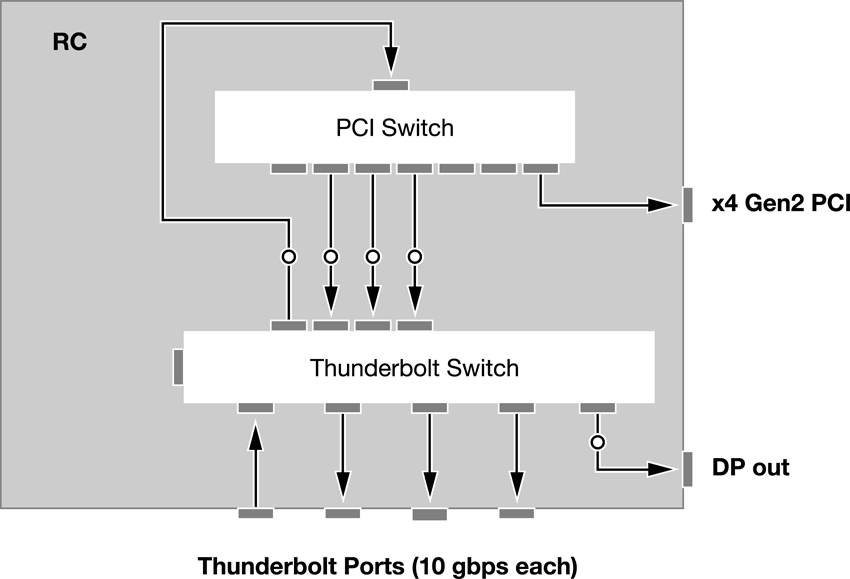
In endpoint mode, the controller chip provides a Gen2 x4 downlink (supports x1, x2, x4 at Gen2 speeds) or Gen1 4x1 downlinks to support multiple devices. Figure 1-2 provides an example of the controller chip as an endpoint with both a x4 Gen2 PCI and a DisplayPort (DP) output option.
Using Thunderbolt Communication over Ports
Communication over Thunderbolt ports is achieved by establishing paths between two adapters. A practical example of a PCI expansion chassis as shown in Figure 1-3.
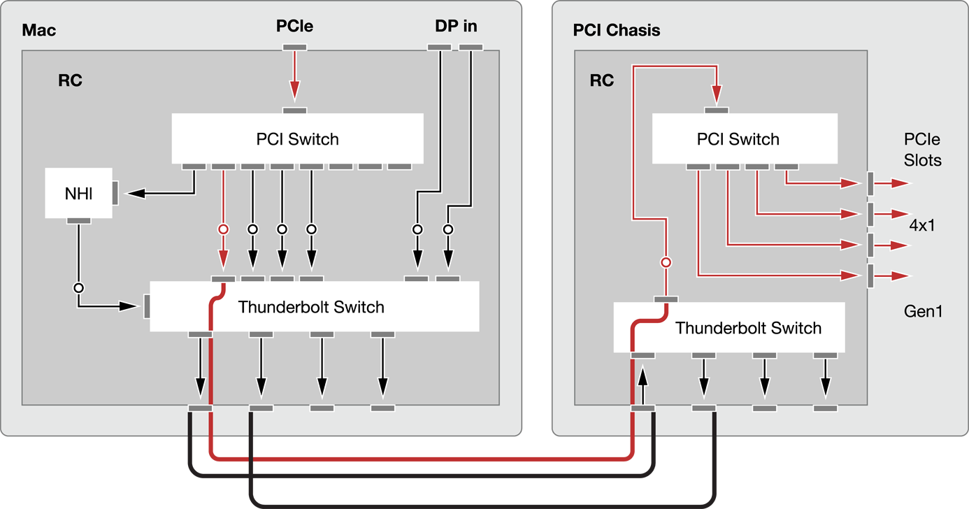
In Figure 1-3, a PCI path has been established by routing the PCI upstream connection from the PCI switch in the Mac host through the Thunderbolt switch and across the cable to the Thunderbolt switch in the PCI chassis. From the Thunderbolt switch inside the PCI chassis, the path is routed up to the PCI switch in the controller chip. The PCI fanout from the switch provides 4x1 connectivity.
PCI paths can utilize fanout or can connect directly to PCI adapters in the Mac host. The host software controls how the paths are established. Wherever possible, OS X and EFI attempt to use the same algorithms for path selection to provide a similar user experience. Devices can also provide hints to software, indicating how much and the type of bandwidth the device consumes in order for the software to make a more optimal selection. An example of fanout is shown in Figure 1-4.

The disk labeled Disk #1 has a PCI switch inside the controller chip used for fanout. In Figure 1-5, the host software can connect Disk #2 directly to the host, instead of using fanout.
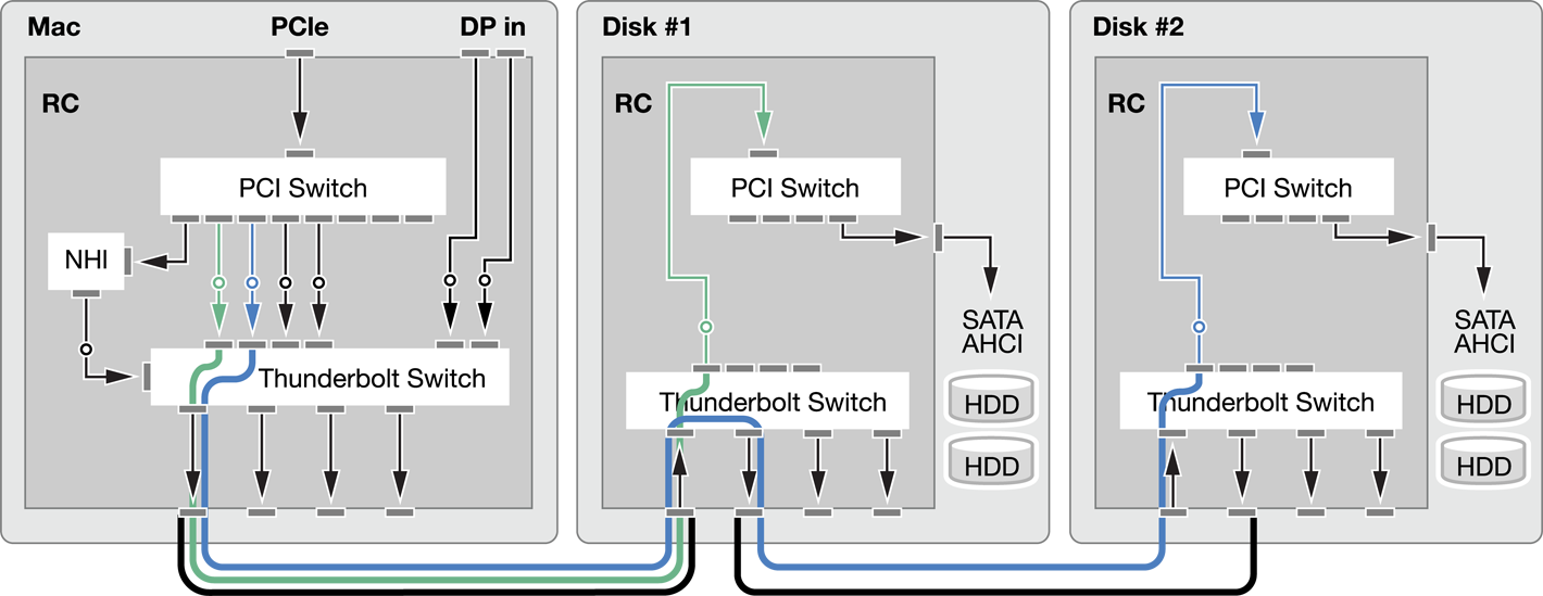
Only four PCI adapters are available through the Mac host. The host determines the optimal routes for all of the attached devices.
Copyright © 2013 Apple Inc. All Rights Reserved. Terms of Use | Privacy Policy | Updated: 2013-10-22