Tessellation
Available in: iOS_GPUFamily3_v2, OSX_GPUFamily1_v2
Tessellation is used to calculate a more detailed surface from an initial surface constructed with quad or triangle patches made up of control points. To approximate the high-order surface, the GPU uses per-patch tessellation factors to subdivide each patch into triangles
Metal Tessellation Pipeline
Figure 12-1 shows the Metal tessellation pipeline, which uses a compute kernel, tessellator, and post-tessellation vertex function.
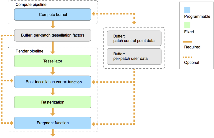
Tessellation operates on patches, with each patch representing an arbitrary arrangement of geometry defined by a collection of control points. Per-patch tessellation factors, per-patch user data, and patch control point data are each stored in separate MTLBuffer objects.
Compute Kernel
The compute kernel is a kernel function that performs the following operations:
Computes per-patch tessellation factors.
Optionally, computes per-patch user data.
Optionally, computes or modifies patch control point data.
Tessellator
The tessellator is a fixed-function pipeline stage that creates a sampling pattern of the patch surface and generates graphics primitives that connect these samples. The tessellator tiles a canonical domain in a normalized coordinate system, ranging from 0.0 to 1.0.
The tessellator is configured as part of your render pipeline, using a MTLRenderPipelineDescriptor object to build a MTLRenderPipelineState object. The inputs to the tessellator are the per-patch tessellation factors.
Tessellator Primitive Generation
The tessellator runs once per patch, consuming the input patch and producing a new set of triangles. These triangles are produced by subdividing the patch according to the per-patch tessellation factors provided. Each triangle vertex produced by the tessellator has an associated (u, v) or (u, v, w) position in normalized parameter space, with each parameter value ranging from 0.0 to 1.0. (Note that subdivision is performed in an implementation-dependent manner.)
Post-Tessellation Vertex Function
The post-tessellation vertex function is a vertex function that calculates the vertex data for each patch surface sample produced by the tessellator. The inputs to the post-tessellation vertex function are:
The normalized vertex coordinates on the patch (output by the tessellator).
The per-patch user data (optionally output by the compute kernel).
The patch control point data (optionally output by the compute kernel).
Any other vertex function inputs, such as textures and buffers.
The post-tessellation vertex function generates the final vertex data for the tessellated triangles. After the post-tessellation vertex function has completed execution, the tessellated primitives are rasterized and the remaining stages of the render pipeline are executed as normal.
Per-Patch Tessellation Factors
Per-patch tessellation factors specify how much each patch is subdivided by the tessellator. Per-patch tessellation factors are described by the MTLQuadTessellationFactorsHalf structure for a quad patch or the MTLTriangleTessellationFactorsHalf structure for a triangle patch.
Understanding Quad Patches
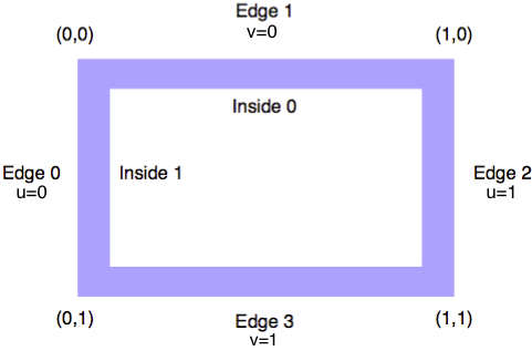
For quad patches, the position in the patch is a (u, v) cartesian coordinate that indicates the horizontal and vertical position of the vertex relative to the quad patch bounds, as shown in Figure 12-2. The (u, v) values range from 0.0 to 1.0 each.
Interpreting the MTLQuadTessellationFactorsHalf structure
The MTLQuadTessellationFactorsHalf structure is defined as follows:
typedef struct { |
uint16_t edgeTessellationFactor[4]; |
uint16_t insideTessellationFactor[2]; |
} MTLQuadTessellationFactorsHalf; |
Each value in the structure provides a specific tessellation factor:
edgeTessellationFactor[0]provides the tessellation factor for the edge of the patch whereu=0(edge 0).edgeTessellationFactor[1]provides the tessellation factor for the edge of the patch wherev=0(edge 1).edgeTessellationFactor[2]provides the tessellation factor for the edge of the patch whereu=1(edge 2).edgeTessellationFactor[3]provides the tessellation factor for the edge of the patch wherev=1(edge 3).insideTessellationFactor[0]provides the horizontal tessellation factor for all internal values ofv.insideTessellationFactor[1]provides the vertical tessellation factor for all internal values ofu.
Understanding Triangle Patches
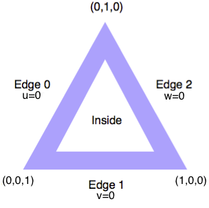
For triangle patches, the position in the patch is a (u, v, w) barycentric coordinate that indicates the relative influence of the three vertices of the triangle on the position of the vertex, as shown in Figure 12-3. The (u, v, w) values range from 0.0 to 1.0 each, where u+v+w=1.0.
Interpreting the MTLTriangleTessellationFactorsHalf structure
The MTLTriangleTessellationFactorsHalf structure is defined as follows:
typedef struct { |
uint16_t edgeTessellationFactor[3]; |
uint16_t insideTessellationFactor; |
} MTLTriangleTessellationFactorsHalf; |
Each value in the structure provides a specific tessellation factor:
edgeTessellationFactor[0]provides the tessellation factor for the edge of the patch whereu=0(edge 0).edgeTessellationFactor[1]provides the tessellation factor for the edge of the patch wherev=0(edge 1).edgeTessellationFactor[2]provides the tessellation factor for the edge of the patch wherew=1(edge 2).insideTessellationFactorprovides the inside tessellation factor.
Rules for Discarding Patches
If the value of an edge tessellation factor is either negative, zero, or corresponds to a floating-point NaN, the tessellator discards the patch. If the value of an inside tessellation factor is negative, the tessellation factor is clamped to the range defined by the tessellationPartitionMode property and the tessellator does not discard the patch.
If the patch is not discarded and the tessellationFactorScaleEnabled property is set to YES, the tessellator multiplies the edge and inside tessellation factors by the scale factor specified in the setTessellationFactorScale: method.
When a patch is discarded, no new primitives are generated, the post-tessellation vertex function does not execute, and no visible output is produced for that patch.
Specifying the Per-Patch Tessellation Factors Buffer
Per-patch tessellation factors are written into a MTLBuffer object and passed as an input to the tessellator by calling the setTessellationFactorBuffer:offset:instanceStride: method. You must call this method before issuing a patch draw call to the same MTLRenderCommandEncoder object.
Patch Functions
This section summarizes the main changes to the Metal shading language to support tessellation. For further information, see the Functions, Variables, and Qualifiers chapter of the Metal Shading Language Guide.
Creating a Compute Kernel
A compute kernel is a kernel function identified by using the existing kernel function qualifier. Listing 12-1 is an example of a compute kernel function signature.
Listing 12-1 Compute kernel function signature
kernel void my_compute_kernel(...) {...} |
Compute kernels are fully supported by the existing features of the Metal shading language. The inputs and outputs of a compute kernel function are the same as a regular kernel function.
Creating a Post-Tessellation Vertex Function
A post-tessellation vertex function is a vertex function identified by using the existing vertex function qualifier. Additionally, the new [[patch(patch-type), N]] attribute is used to specify the patch type (patch-type) and the number of control points in the patch (N). Listing 12-2 is an example of a post-tessellation vertex function signature.
Listing 12-2 Post-tessellation vertex function signature
[[patch(quad, 16)]] |
vertex float4 my_post_tessellation_vertex_function(...) {...} |
Post-Tessellation Vertex Function Inputs
All inputs to a post-tessellation vertex function are passed as one or more of the following arguments:
Resources such as buffers (declared in the
deviceorconstantaddress space), textures, or samplers.Per-patch data and patch control point data. These are either read directly from buffers or are passed to the post-tessellation vertex function as inputs declared with the
[[stage_in]]qualifier.Built-in variables, listed in Table 12-1.
Table 12-1 Attribute qualifiers for post-tessellation vertex function input arguments Attribute qualifier
Corresponding data type
Description
[[patch_id]]ushortoruintThe patch identifier.
[[instance_id]]ushortoruintThe per-instance identifier, which includes the base instance value, if one is specified.
[[base_instance]]ushortoruintThe base instance value added to each instance identifier, before reading per-instance data.
[[position_in_patch]]float2orfloat3Defines the location on the patch being evaluated. For quad patches, must be
float2. For triangle patches, must befloat3.
Post-Tessellation Vertex Function Outputs
The outputs of a post-tessellation vertex function are the same as a regular vertex function. If a post-tessellation vertex function writes to a buffer, its return type must be void.
Tessellation Pipeline State
This section summarize the main changes to the Metal framework API to support tessellation, pertaining to the tessellation pipeline state.
Building a Compute Pipeline
The compute kernel is specified as part of your compute pipeline when building a MTLComputePipelineState object, as demonstrated in Listing 12-3. For best performance, the compute kernel should be executed as early as possible in your frame. (There are no changes to the existing compute pipeline API in order to support compute kernels or tessellation.)
Listing 12-3 Building a compute pipeline with a compute kernel
// Fetch the compute kernel from the library |
id <MTLFunction> computeKernel = [_library newFunctionWithName:@"my_compute_kernel"]; |
// Build the compute pipeline |
NSError *pipelineError = NULL; |
_computePipelineState = [_device newComputePipelineStateWithFunction:computeKernel error:&pipelineError]; |
if (!_computePipelineState) { |
NSLog(@"Failed to create compute pipeline state, error: %@", pipelineError); |
} |
Building a Render Pipeline
The tessellator is configured as part of your render pipeline, using a MTLRenderPipelineDescriptor object to build a MTLRenderPipelineState object. The post-tessellation vertex function is specified with the vertexFunction property. Listing 12-4 demonstrates how to configure and build a render pipeline with a tessellator and a post-tessellation vertex function. For further information, see the Specifying Tessellation State and MTLTessellationFactorStepFunction section of the MTLRenderPipelineDescriptor class reference.
Listing 12-4 Building a render pipeline with a tessellator and a post-tessellation vertex function
// Fetch the post-tessellation vertex function from the library |
id <MTLFunction> postTessellationVertexFunction = [_library newFunctionWithName:@"my_post_tessellation_vertex_function"]; |
// Fetch the fragment function from the library |
id <MTLFunction> fragmentFunction = [_library newFunctionWithName:@"my_fragment_function"]; |
// Configure the render pipeline, using the default tessellation values |
MTLRenderPipelineDescriptor *renderPipelineDescriptor = [MTLRenderPipelineDescriptor new]; |
renderPipelineDescriptor.colorAttachments[0].pixelFormat = _view.colorPixelFormat; |
renderPipelineDescriptor.fragmentFunction = fragmentFunction; |
renderPipelineDescriptor.vertexFunction = postTessellationVertexFunction; |
renderPipelineDescriptor.maxTessellationFactor = 16; |
renderPipelineDescriptor.tessellationFactorScaleEnabled = NO; |
renderPipelineDescriptor.tessellationFactorFormat = MTLTessellationFactorFormatHalf; |
renderPipelineDescriptor.tessellationControlPointIndexType = MTLTessellationControlPointIndexTypeNone; |
renderPipelineDescriptor.tessellationFactorStepFunction = MTLTessellationFactorStepFunctionConstant; |
renderPipelineDescriptor.tessellationOutputWindingOrder = MTLWindingClockwise; |
renderPipelineDescriptor.tessellationPartitionMode = MTLTessellationPartitionModePow2; |
// Build the render pipeline |
NSError *pipelineError = NULL; |
_renderPipelineState = [_device newRenderPipelineStateWithDescriptor:renderPipelineDescriptor error:&pipelineError]; |
if (!_renderPipelineState) { |
NSLog(@"Failed to create render pipeline state, error %@", pipelineError); |
} |
Patch Draw Calls
This section summarize the main changes to the Metal framework API to support tessellation, pertaining to the patch draw calls.
Drawing Tessellated Patches
To render a number of instances of tessellated patches, call one of these MTLRenderCommandEncoder methods:
For all patch draw calls, the per-patch data and an array of patch control points are organized for rendering in contiguous array elements, starting from the value specified in the baseInstance parameter. For further information about each parameter, see the Drawing Tessellated Patches section of the MTLRenderCommandEncoder protocol reference.
To render patch data, the patch draw calls fetch per-patch data and patch control point data. Patch data is typically stored together for all patches of one or more meshes in one or more buffers. A compute kernel is executed to generate the scene-dependent per-patch tessellation factors; the compute kernel may decide to generate factors only for patches that are not discarded, in which case the patches are not contiguous. A patch index buffer is therefore used to identify the patch IDs of patches to be drawn.
A buffer index (drawPatchIndex) in the range from [patchStart, patchStart+patchCount-1] is used to reference data. In cases where the patch indices used to fetch the per-patch data and patch control point data are not contiguous, drawPatchIndex can reference patchIndexBuffer, as seen in Figure 12-4.
patchIndexBuffer to fetch per-patch data and patch control point data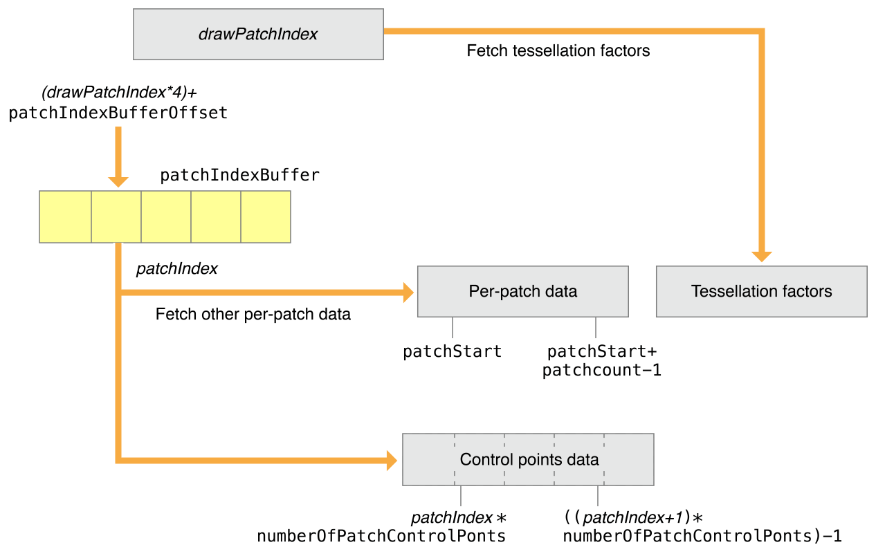
Each element of patchIndexBuffer contains a 32-bit patchIndex value that references the per-patch data and patch control point data. The patchIndex fetched from patchIndexBuffer is at the location: (drawPatchIndex * 4) + patchIndexBufferOffset.
The control point indices for the patch are computed by:
patchIndex * numberOfPatchControlPoints * ((patchIndex + 1) * numberOfPatchControlPoints) - 1
patchIndexBuffer also enables the patchIndex used to read the per-patch data and patch control point data to be different from the index used to read the per-patch tessellation factors. For the tessellator, drawPatchIndex is directly used as an index to fetch per-patch tessellation factors.
If patchIndexBuffer is NULL, the drawPatchIndex and patchIndex are the same value, as shown in Figure 12-5.
patchIndexBuffer is NULL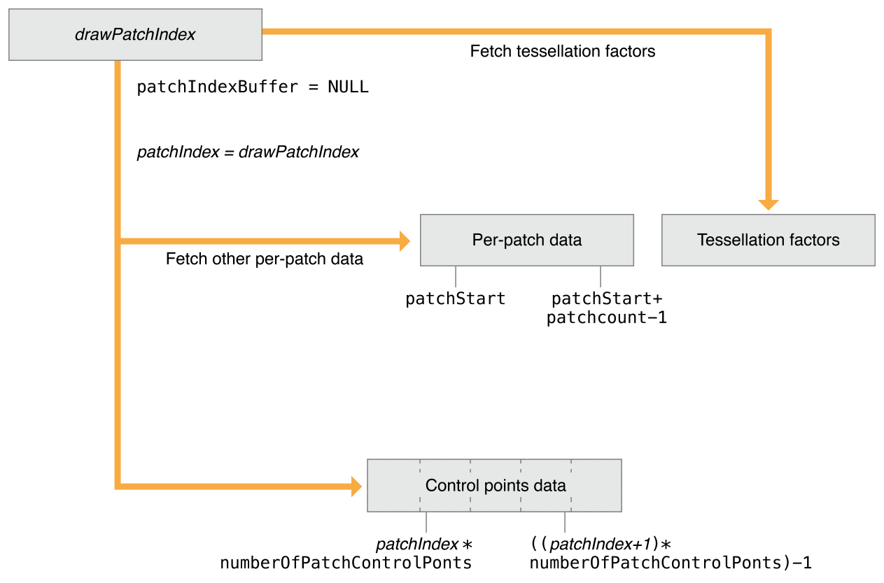
In cases where control points are shared across patches or the patch control point data is not contiguous, use the drawIndexedPatches method. patchIndex references a specified controlPointIndexBuffer, which contains the control point indices of a patch as seen in Figure 12-6. (tessellationControlPointIndexType describes the size of the control point indices in controlPointIndexBuffer and must be either MTLTessellationControlPointIndexTypeUInt16 or MTLTessellationControlPointIndexTypeUInt32.)
controlPointIndexBuffer to fetch patch control point data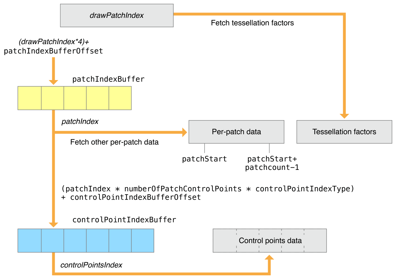
The actual location of the first control point index in controlPointIndexBuffer is computed as:
controlPointIndexBufferOffset + (patchIndex * numberOfPatchControlPoints * controlPointIndexType == UInt16 ? 2 : 4)
Several (numberOfPatchControlPoints) control point indices must be stored consecutively in controlPointIndexBuffer, starting at the location of the first control point index.
Sample Code
For an example of how to set up a basic tessellation pipeline, see the MetalBasicTessellation sample.
Porting DirectX 11-Style Tessellation Shaders to Metal
This section describes how to port a DirectX 11-style tessellation vertex and hull shader to a Metal compute kernel.
In DirectX 11, the HLSL vertex shader is executed for each control point of a patch. The HLSL hull shader is specified by two functions: a function that executes for each control point of the patch and another that executes per-patch. The output of the vertex shader is input to these two functions that make up the hull shader.
Listing 12-5 shows a simple HLSL vertex and hull shader.
Listing 12-5 Simple HLSL vertex and hull shader
struct VertexIn |
{ |
float3 PosL; |
float3 NormalL; |
float3 TangentL; |
float2 Tex; |
}; |
struct VertexOut |
{ |
float3 PosW : POSITION; |
float3 NormalW : NORMAL; |
float3 TangentW : TANGENT; |
float2 Tex : TEXCOORD; |
float TessFactor : TESS; |
}; |
VertexOut VS(VertexIn vin) |
{ |
VertexOut vout; |
// Transform to world space space. |
vout.PosW = mul(float4(vin.PosL, 1.0f), gWorld).xyz; |
vout.NormalW = mul(vin.NormalL, (float3x3)gWorldInvTranspose); |
vout.TangentW = mul(vin.TangentL, (float3x3)gWorld); |
// Output vertex attributes for interpolation across triangle. |
vout.Tex = mul(float4(vin.Tex, 0.0f, 1.0f), gTexTransform).xy; |
float d = distance(vout.PosW, gEyePosW); |
// Normalized tessellation factor. |
// The tessellation is |
// 0 if d >= gMinTessDistance and |
// 1 if d <= gMaxTessDistance. |
float tess = saturate( (gMinTessDistance - d) / |
(gMinTessDistance - gMaxTessDistance) ); |
// Rescale [0,1] --> [gMinTessFactor, gMaxTessFactor]. |
vout.TessFactor = gMinTessFactor + tess*(gMaxTessFactor-gMinTessFactor); |
return vout; |
} |
struct HullOut |
{ |
float3 PosW : POSITION; |
float3 NormalW : NORMAL; |
float3 TangentW : TANGENT; |
float2 Tex : TEXCOORD; |
}; |
[domain("tri")] |
[partitioning("fractional_odd")] |
[outputtopology("triangle_cw")] |
[outputcontrolpoints(3)] |
[patchconstantfunc("PatchHS")] |
HullOut HS(InputPatch<VertexOut,3> p, |
uint i : SV_OutputControlPointID, |
uint patchId : SV_PrimitiveID) |
{ |
HullOut hout; |
// Pass through shader. |
hout.PosW = p[i].PosW; |
hout.NormalW = p[i].NormalW; |
hout.TangentW = p[i].TangentW; |
hout.Tex = p[i].Tex; |
return hout; |
} |
struct PatchTess |
{ |
float EdgeTess[3] : SV_TessFactor; |
float InsideTess : SV_InsideTessFactor; |
}; |
PatchTess PatchHS(InputPatch<VertexOut,3> patch, |
uint patchID : SV_PrimitiveID) |
{ |
PatchTess pt; |
// Average tess factors along edges, and pick an edge tess factor for |
// the interior tessellation. It is important to do the tess factor |
// calculation based on the edge properties so that edges shared by |
// more than one triangle will have the same tessellation factor. |
// Otherwise, gaps can appear. |
pt.EdgeTess[0] = 0.5f*(patch[1].TessFactor + patch[2].TessFactor); |
pt.EdgeTess[1] = 0.5f*(patch[2].TessFactor + patch[0].TessFactor); |
pt.EdgeTess[2] = 0.5f*(patch[0].TessFactor + patch[1].TessFactor); |
pt.InsideTess = pt.EdgeTess[0]; |
return pt; |
} |
These simple HLSL vertex and hull shaders can be ported to Metal functions, and a compute kernel that calls these Metal functions can be created that executes these functions as a single kernel. The ported vertex and control point hull functions are called per-thread in the compute kernel, followed by a threadgroup barrier, and then the per-patch hull function is executed by a subset of the threads in the threadgroup. Being able to directly call the translated vertex and hull functions in the kernel makes it really easy for developers to port their vertex and hull shaders from DirectX 11 to Metal.
The simple HLSL vertex and hull shaders can be ported to the Metal functions shown in Listing 12-6.
Listing 12-6 Simple HLSL vertex and hull shader ported to Metal functions
struct VertexIn |
{ |
float3 PosL [[ attribute(0) ]]; |
float3 NormalL [[ attribute(1) ]]; |
float3 TangentL [[ attribute(2) ]]; |
float2 Tex [[ attribute(3) ]]; |
}; |
struct VertexOut |
{ |
float3 PosW [[ position ]]; |
float3 NormalW; |
float3 TangentW; |
float2 Tex; |
float TessFactor; |
}; |
struct ConstantData { |
…; |
} |
// The vertex control point function |
VertexOut |
VS(VertexIn vin, |
constant ConstantData &c) |
{ |
VertexOut vout; |
// Transform to world space space. |
vout.PosW = mul(float4(vin.PosL, 1.0f), c.gWorld).xyz; |
vout.NormalW = mul(vin.NormalL, (float3x3)c.gWorldInvTranspose); |
vout.TangentW = mul(vin.TangentL, (float3x3)c.gWorld); |
// Output vertex attributes for interpolation across triangle. |
vout.Tex = mul(float4(vin.Tex, 0.0f, 1.0f), c.gTexTransform).xy; |
float d = distance(vout.PosW, gEyePosW); |
// Normalized tessellation factor. |
// The tessellation is |
// 0 if d >= gMinTessDistance and |
// 1 if d <= gMaxTessDistance. |
float tess = saturate( (c.gMinTessDistance - d) / |
(c.gMinTessDistance - c.gMaxTessDistance) ); |
// Rescale [0,1] --> [gMinTessFactor, gMaxTessFactor]. |
vout.TessFactor = c.gMinTessFactor + |
tess * (c.gMaxTessFactor - c.gMinTessFactor); |
return vout; |
} |
struct HullOut |
{ |
float3 PosW [[ position ]]; |
float3 NormalW; |
float3 TangentW; |
float2 Tex; |
} |
// The patch control point function |
HullOut |
HS(VertexOut p) |
{ |
HullOut hout; |
// Pass through shader. |
hout.PosW = p.PosW; |
hout.NormalW = p.NormalW; |
hout.TangentW = p.TangentW; |
hout.Tex = p.Tex; |
return hout; |
} |
struct PatchTess |
{ |
packed_half3 EdgeTess; |
half InsideTess; |
}; |
// The per-patch function |
PatchTess |
PatchHS(threadgroup VertexOut *patch) |
{ |
PatchTess pt; |
// Average tess factors along edges, and pick an edge tess factor for |
// the interior tessellation. It is important to do the tess factor |
// calculation based on the edge properties so that edges shared by |
// more than one triangle will have the same tessellation factor. |
// Otherwise, gaps can appear. |
pt.EdgeTess[0] = 0.5f*(patch[1].TessFactor + patch[2].TessFactor); |
pt.EdgeTess[1] = 0.5f*(patch[2].TessFactor + patch[0].TessFactor); |
pt.EdgeTess[2] = 0.5f*(patch[0].TessFactor + patch[1].TessFactor); |
pt.InsideTess = pt.EdgeTess[0]; |
return pt; |
} |
A compute kernel that calls these vertex and hull functions can be: |
struct KernelPatchInfo { |
uint numPatches; // total number of patches to process. |
// we need this because this value may |
// not be a multiple of threadgroup size. |
ushort numPatchesInThreadGroup; // number of patches processed by a |
// thread-group |
ushort numControlPointsPerPatch; |
}; // passed as a constant buffer using setBytes by the runtime |
kernel void |
PatchKernel(VertexIn vIn [[ stage_in ]], |
constant ConstantData &c [[ buffer(1) ]], |
constant KernelPatchInfo &patchInfo [[ buffer(2) ]], |
PatchTess *tessellationFactorBuffer [[ buffer(3) ]], |
device HullOut *hullOutputBuffer [[ buffer(4) ]], |
threadgroup HullOut *hullOutputTGBuffer [[ threadgroup(0) ]], |
uint tID [[ thread_position_in_grid ]], |
ushort lID [[ thread_position_in_threadgroup ]], |
ushort lSize [[ threads_in_threadgroup ]], |
ushort groupID [[ threadgroup_position_in_grid ]]) |
{ |
ushort n = patchInfo.numControlPointsPerPatch; |
uint patchGroupID = groupID * patchInfo.numPatchesInThreadGroup; |
// execute the vertex and control-point hull function per-thread |
if ( (lID <= (patchInfo.numPatchesInThreadGroup * n) && |
(tID <= (patchInfo.numPatches * n)) ) |
{ |
uint controlPointID = patchGroupID * n + lID; |
VertexOut vOut = VS(vIn, c); |
HullOut hOut = HS(vOut); |
hullOutputTGBuffer[lID] = hOut; |
hullOutputBuffer[controlPointID] = hOut; |
} |
threadgroup_barrier(mem_flags::mem_threadgroup); |
// execute the per-patch hull function |
if (lID < patchInfo.numPatchesInThreadGroup) |
{ |
uint patchID = patchGroupID + lID; |
tessellationFactorBuffer[patchID] = PatchHS( |
hullOutputTGBuffer[lID*n]); |
} |
} |
Copyright © 2016 Apple Inc. All Rights Reserved. Terms of Use | Privacy Policy | Updated: 2016-12-12