Retired Document
Important: OpenGL ES was deprecated in iOS 12. To create high-performance code on GPUs, use the Metal framework instead. See Metal.
Best Practices for Working with Vertex Data
To render a frame using OpenGL ES your app configures the graphics pipeline and submits graphics primitives to be drawn. In some apps, all primitives are drawn using the same pipeline configuration; other apps may render different elements of the frame using different techniques. But no matter which primitives you use in your app or how the pipeline is configured, your app provides vertices to OpenGL ES. This chapter provides a refresher on vertex data and follows it with targeted advice for how to efficiently process vertex data.
A vertex consists of one or more attributes, such as the position, the color, the normal, or texture coordinates. An OpenGL ES 2.0 or 3.0 app is free to define its own attributes; each attribute in the vertex data corresponds to an attribute variable that acts as an input to the vertex shader. An OpenGL 1.1 app uses attributes defined by the fixed-function pipeline.
You define an attribute as a vector consisting of one to four components. All components in the attribute share a common data type. For example, a color might be defined as four GLubyte components (red, green, blue, alpha). When an attribute is loaded into a shader variable, any components that are not provided in the app data are filled in with default values by OpenGL ES. The last component is filled with 1, and other unspecified components are filled with 0, as illustrated in Figure 8-1.
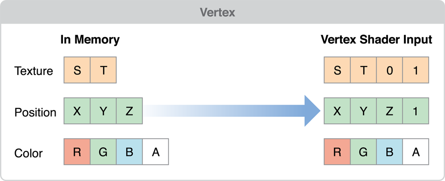
Your app may configure an attribute to be a constant, which means the same values are used for all vertices submitted as part of a draw command, or an array, which means that each vertex a value for that attribute. When your app calls a function in OpenGL ES to draw a set of vertices, the vertex data is copied from your app to the graphics hardware. The graphics hardware than acts on the vertex data, processing each vertex in the shader, assembling primitives and rasterizing them out into the framebuffer. One advantage of OpenGL ES is that it standardizes on a single set of functions to submit vertex data to OpenGL ES, removing older and less efficient mechanisms that were provided by OpenGL.
Apps that must submit a large number of primitives to render a frame need to carefully manage their vertex data and how they provide it to OpenGL ES. The practices described in this chapter can be summarized in a few basic principles:
Reduce the size of your vertex data.
Reduce the pre-processing that must occur before OpenGL ES can transfer the vertex data to the graphics hardware.
Reduce the time spent copying vertex data to the graphics hardware.
Reduce computations performed for each vertex.
Simplify Your Models
The graphics hardware of iOS-based devices is very powerful, but the images it displays are often very small. You don’t need extremely complex models to present compelling graphics on iOS. Reducing the number of vertices used to draw a model directly reduces the size of the vertex data and the calculations performed on your vertex data.
You can reduce the complexity of a model by using some of the following techniques:
Provide multiple versions of your model at different levels of detail, and choose an appropriate model at runtime based on the distance of the object from the camera and the dimensions of the display.
Use textures to eliminate the need for some vertex information. For example, a bump map can be used to add detail to a model without adding more vertex data.
Some models add vertices to improve lighting details or rendering quality. This is usually done when values are calculated for each vertex and interpolated across the triangle during the rasterization stage. For example, if you directed a spotlight at the center of a triangle, its effect might go unnoticed because the brightest part of the spotlight is not directed at a vertex. By adding vertices, you provide additional interpolant points, at the cost of increasing the size of your vertex data and the calculations performed on the model. Instead of adding additional vertices, consider moving calculations into the fragment stage of the pipeline instead:
If your app uses OpenGL ES 2.0 or later, then your app performs the calculation in the vertex shader and assigns it to a varying variable. The varying value is interpolated by the graphics hardware and passed to the fragment shader as an input. Instead, assign the calculation’s inputs to varying variables and perform the calculation in the fragment shader. Doing this changes the cost of performing that calculation from a per-vertex cost to a per-fragment cost, reduces pressure on the vertex stage and more pressure on the fragment stage of the pipeline. Do this when your app is blocked on vertex processing, the calculation is inexpensive and the vertex count can be significantly reduced by the change.
If your app uses OpenGL ES 1.1, you can perform per-fragment lighting using DOT3 lighting. You do this by adding a bump map texture to hold normal information and applying the bump map using a texture combine operation with the
GL_DOT3_RGBmode.
Avoid Storing Constants in Attribute Arrays
If your models include attributes that uses data that remains constant across the entire model, do not duplicate that data for each vertex. OpenGL ES 2.0 and 3.0 apps can either set a constant vertex attribute or use a uniform shader value to hold the value instead. OpenGL ES 1.1 app should use a per-vertex attribute function such as glColor4ub or glTexCoord2f instead.
Use the Smallest Acceptable Types for Attributes
When specifying the size of each of your attribute’s components, choose the smallest data type that provides acceptable results. Here are some guidelines:
Specify vertex colors using four unsigned byte components (
GL_UNSIGNED_BYTE).Specify texture coordinates using 2 or 4 unsigned bytes (
GL_UNSIGNED_BYTE) or unsigned short (GL_UNSIGNED_SHORT). Do not pack multiple sets of texture coordinates into a single attribute.Avoid using the OpenGL ES
GL_FIXEDdata type. It requires the same amount of memory asGL_FLOAT, but provides a smaller range of values. All iOS devices support hardware floating-point units, so floating point values can be processed more quickly.OpenGL ES 3.0 contexts support a wider range of small data types, such as
GL_HALF_FLOATandGL_INT_2_10_10_10_REV. These often provide sufficient precision for attributes such as normals, with a smaller footprint thanGL_FLOAT.
If you specify smaller components, be sure you reorder your vertex format to avoid misaligning your vertex data. See Avoid Misaligned Vertex Data.
Use Interleaved Vertex Data
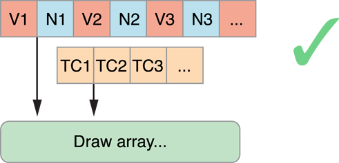
You can specify vertex data as a series of arrays (also known as a struct of arrays) or as an array where each element includes multiple attributes (an array of structs). The preferred format on iOS is an array of structs with a single interleaved vertex format. Interleaved data provides better memory locality for each vertex.

An exception to this rule is when your app needs to update some vertex data at a rate different from the rest of the vertex data, or if some data can be shared between two or more models. In either case, you may want to separate the attribute data into two or more structures.
Avoid Misaligned Vertex Data
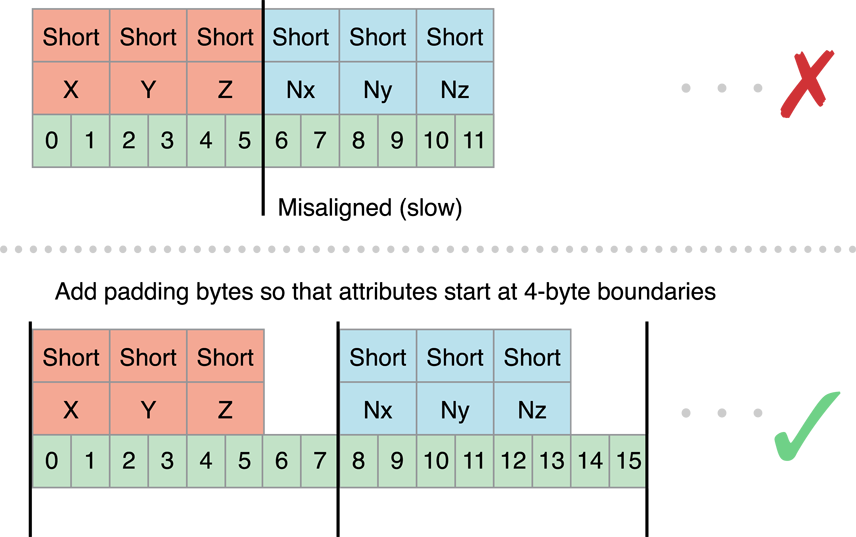
When you are designing your vertex structure, align the beginning of each attribute to an offset that is either a multiple of its component size or 4 bytes, whichever is larger. When an attribute is misaligned, iOS must perform additional processing before passing the data to the graphics hardware.
In Figure 8-4, the position and normal data are each defined as three short integers, for a total of six bytes. The normal data begins at offset 6, which is a multiple of the native size (2 bytes), but is not a multiple of 4 bytes. If this vertex data were submitted to iOS, iOS would have to take additional time to copy and align the data before passing it to the hardware. To fix this, explicitly add two bytes of padding after each attribute.
Use Triangle Strips to Batch Vertex Data
Using triangle strips significantly reduces the number of vertex calculations that OpenGL ES must perform on your models. On the left side of Figure 8-5, three triangles are specified using a total of nine vertices. C, E and G actually specify the same vertex! By specifying the data as a triangle strip, you can reduce the number of vertices from nine to five.

Sometimes, your app can combine more than one triangle strip into a single larger triangle strip. All of the strips must share the same rendering requirements. This means:
You must use the same shader to draw all of the triangle strips.
You must be able to render all of the triangle strips without changing any OpenGL state.
The triangle strips must share the same vertex attributes.
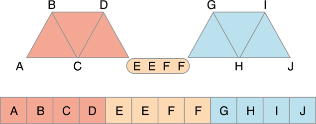
To merge two triangle strips, duplicate the last vertex of the first strip and the first vertex of the second strip, as shown in Figure 8-6. When this strip is submitted to OpenGL ES, triangles DEE, EEF, EFF, and FFG are considered degenerate and not processed or rasterized.
For best performance, your models should be submitted as a single indexed triangle strip. To avoid specifying data for the same vertex multiple times in the vertex buffer, use a separate index buffer and draw the triangle strip using the glDrawElements function (or the glDrawElementsInstanced or glDrawRangeElements functions, if appropriate).
In OpenGL ES 3.0, you can use the primitive restart feature to merge triangle strips without using degenerate triangles. When this feature is enabled, OpenGL ES treats the largest possible value in an index buffer as a command to finish one triangle strip and start another. Listing 8-1 demonstrates this approach.
Listing 8-1 Using primitive restart in OpenGL ES 3.0
// Prepare index buffer data (not shown: vertex buffer data, loading vertex and index buffers) |
GLushort indexData[11] = { |
0, 1, 2, 3, 4, // triangle strip ABCDE |
0xFFFF, // primitive restart index (largest possible GLushort value) |
5, 6, 7, 8, 9, // triangle strip FGHIJ |
}; |
// Draw triangle strips |
glEnable(GL_PRIMITIVE_RESTART_FIXED_INDEX); |
glDrawElements(GL_TRIANGLE_STRIP, 11, GL_UNSIGNED_SHORT, 0); |
Where possible, sort vertex and index data so triangles that share common vertices are drawn reasonably close to each other in the triangle strip. Graphics hardware often caches recent vertex calculations to avoid recalculating a vertex.
Use Vertex Buffer Objects to Manage Copying Vertex Data
Listing 8-2 provides a function that a simple app might use to provide position and color data to the vertex shader. It enables two attributes and configures each to point at the interleaved vertex structure. Finally, it calls the glDrawElements function to render the model as a single triangle strip.
Listing 8-2 Submitting vertex data to a shader program
typedef struct _vertexStruct |
{ |
GLfloat position[2]; |
GLubyte color[4]; |
} vertexStruct; |
void DrawModel() |
{ |
const vertexStruct vertices[] = {...}; |
const GLubyte indices[] = {...}; |
glVertexAttribPointer(GLKVertexAttribPosition, 2, GL_FLOAT, GL_FALSE, |
sizeof(vertexStruct), &vertices[0].position); |
glEnableVertexAttribArray(GLKVertexAttribPosition); |
glVertexAttribPointer(GLKVertexAttribColor, 4, GL_UNSIGNED_BYTE, GL_TRUE, |
sizeof(vertexStruct), &vertices[0].color); |
glEnableVertexAttribArray(GLKVertexAttribColor); |
glDrawElements(GL_TRIANGLE_STRIP, sizeof(indices)/sizeof(GLubyte), GL_UNSIGNED_BYTE, indices); |
} |
This code works, but is inefficient. Each time DrawModel is called, the index and vertex data are copied to OpenGL ES, and transferred to the graphics hardware. If the vertex data does not change between invocations, these unnecessary copies can impact performance. To avoid unnecessary copies, your app should store its vertex data in a vertex buffer object (VBO). Because OpenGL ES owns the vertex buffer object’s memory, it can store the buffer in memory that is more accessible to the graphics hardware, or pre-process the data into the preferred format for the graphics hardware.
Listing 8-3 creates a pair of vertex buffer objects, one to hold the vertex data and the second for the strip’s indices. In each case, the code generates a new object, binds it to be the current buffer, and fills the buffer. CreateVertexBuffers would be called when the app is initialized.
Listing 8-3 Creating a vertex buffer object
GLuint vertexBuffer; |
GLuint indexBuffer; |
void CreateVertexBuffers() |
{ |
glGenBuffers(1, &vertexBuffer); |
glBindBuffer(GL_ARRAY_BUFFER, vertexBuffer); |
glBufferData(GL_ARRAY_BUFFER, sizeof(vertices), vertices, GL_STATIC_DRAW); |
glGenBuffers(1, &indexBuffer); |
glBindBuffer(GL_ELEMENT_ARRAY_BUFFER, indexBuffer); |
glBufferData(GL_ELEMENT_ARRAY_BUFFER, sizeof(indices), indices, GL_STATIC_DRAW); |
} |
Listing 8-4 modifies Listing 8-2 to use the vertex buffer objects. The key difference in Listing 8-4 is that the parameters to the glVertexAttribPointer functions no longer point to the vertex arrays. Instead, each is an offset into the vertex buffer object.
Listing 8-4 Drawing with a vertex buffer object
void DrawModelUsingVertexBuffers() |
{ |
glBindBuffer(GL_ARRAY_BUFFER, vertexBuffer); |
glVertexAttribPointer(GLKVertexAttribPosition, 2, GL_FLOAT, GL_FALSE, |
sizeof(vertexStruct), (void *)offsetof(vertexStruct, position)); |
glEnableVertexAttribArray(GLKVertexAttribPosition); |
glVertexAttribPointer(GLKVertexAttribColor, 4, GL_UNSIGNED_BYTE, GL_TRUE, |
sizeof(vertexStruct), (void *)offsetof(vertexStruct, color)); |
glEnableVertexAttribArray(GLKVertexAttribColor); |
glBindBuffer(GL_ELEMENT_ARRAY_BUFFER, indexBuffer); |
glDrawElements(GL_TRIANGLE_STRIP, sizeof(indices)/sizeof(GLubyte), GL_UNSIGNED_BYTE, (void*)0); |
} |
Buffer Usage Hints
The previous example initialized the vertex buffer once and never changed its contents afterwards. You can change the contents of a vertex buffer. A key part of the design of vertex buffer objects is that the app can inform OpenGL ES how it uses the data stored in the buffer. An OpenGL ES implementation can use this hint to alter the strategy it uses for storing the vertex data. In Listing 8-3, each call to the glBufferData function provides a usage hint as the last parameter. Passing GL_STATIC_DRAW into glBufferData tells OpenGL ES that the contents of both buffers are never expected to change, which gives OpenGL ES more opportunities to optimize how and where the data is stored.
The OpenGL ES specification defines the following usage cases:
GL_STATIC_DRAWis for vertex buffers that are rendered many times, and whose contents are specified once and never change.GL_DYNAMIC_DRAWis for vertex buffers that are rendered many times, and whose contents change during the rendering loop.GL_STREAM_DRAWis for vertex buffers that are rendered a small number of times and then discarded.
In iOS, GL_DYNAMIC_DRAW and GL_STREAM_DRAW are equivalent. You can use the glBufferSubData function to update buffer contents, but doing so incurs a performance penalty because it flushes the command buffer and waits for all commands to complete. Double or triple buffering can reduce this performance cost somewhat. (See Use Double Buffering to Avoid Resource Conflicts.) For better performance, use the glMapBufferRange function in OpenGL ES 3.0 or the corresponding function provided by the EXT_map_buffer_range
If different attributes inside your vertex format require different usage patterns, split the vertex data into multiple structures and allocate a separate vertex buffer object for each collection of attributes that share common usage characteristics. Listing 8-5 modifies the previous example to use a separate buffer to hold the color data. By allocating the color buffer using the GL_DYNAMIC_DRAW hint, OpenGL ES can allocate that buffer so that your app maintains reasonable performance.
Listing 8-5 Drawing a model with multiple vertex buffer objects
typedef struct _vertexStatic |
{ |
GLfloat position[2]; |
} vertexStatic; |
typedef struct _vertexDynamic |
{ |
GLubyte color[4]; |
} vertexDynamic; |
// Separate buffers for static and dynamic data. |
GLuint staticBuffer; |
GLuint dynamicBuffer; |
GLuint indexBuffer; |
const vertexStatic staticVertexData[] = {...}; |
vertexDynamic dynamicVertexData[] = {...}; |
const GLubyte indices[] = {...}; |
void CreateBuffers() |
{ |
// Static position data |
glGenBuffers(1, &staticBuffer); |
glBindBuffer(GL_ARRAY_BUFFER, staticBuffer); |
glBufferData(GL_ARRAY_BUFFER, sizeof(staticVertexData), staticVertexData, GL_STATIC_DRAW); |
// Dynamic color data |
// While not shown here, the expectation is that the data in this buffer changes between frames. |
glGenBuffers(1, &dynamicBuffer); |
glBindBuffer(GL_ARRAY_BUFFER, dynamicBuffer); |
glBufferData(GL_ARRAY_BUFFER, sizeof(dynamicVertexData), dynamicVertexData, GL_DYNAMIC_DRAW); |
// Static index data |
glGenBuffers(1, &indexBuffer); |
glBindBuffer(GL_ELEMENT_ARRAY_BUFFER, indexBuffer); |
glBufferData(GL_ELEMENT_ARRAY_BUFFER, sizeof(indices), indices, GL_STATIC_DRAW); |
} |
void DrawModelUsingMultipleVertexBuffers() |
{ |
glBindBuffer(GL_ARRAY_BUFFER, staticBuffer); |
glVertexAttribPointer(GLKVertexAttribPosition, 2, GL_FLOAT, GL_FALSE, |
sizeof(vertexStruct), (void *)offsetof(vertexStruct, position)); |
glEnableVertexAttribArray(GLKVertexAttribPosition); |
glBindBuffer(GL_ARRAY_BUFFER, dynamicBuffer); |
glVertexAttribPointer(GLKVertexAttribColor, 4, GL_UNSIGNED_BYTE, GL_TRUE, |
sizeof(vertexStruct), (void *)offsetof(vertexStruct, color)); |
glEnableVertexAttribArray(GLKVertexAttribColor); |
glBindBuffer(GL_ELEMENT_ARRAY_BUFFER, indexBuffer); |
glDrawElements(GL_TRIANGLE_STRIP, sizeof(indices)/sizeof(GLubyte), GL_UNSIGNED_BYTE, (void*)0); |
} |
Consolidate Vertex Array State Changes Using Vertex Array Objects
Take a closer look at the DrawModelUsingMultipleVertexBuffers function in Listing 8-5. It enables many attributes, binds multiple vertex buffer objects, and configures attributes to point into the buffers. All of that initialization code is essentially static; none of the parameters change from frame to frame. If this function is called every time the app renders a frame, there’s a lot of unnecessary overhead reconfiguring the graphics pipeline. If the app draws many different kinds of models, reconfiguring the pipeline may become a bottleneck. Instead, use a vertex array object to store a complete attribute configuration. Vertex array objects are part of the core OpenGL ES 3.0 specification and are available in OpenGL ES 2.0 and 1.1 through the OES_vertex_array_object
Figure 8-7 shows an example configuration with two vertex array objects. Each configuration is independent of the other; each vertex array object can reference a different set of vertex attributes, which can be stored in the same vertex buffer object or split across several vertex buffer objects.
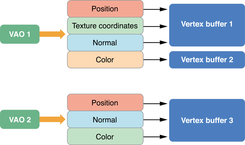
Listing 8-6 provides the code used to configure first vertex array object shown above. It generates an identifier for the new vertex array object and then binds the vertex array object to the context. After this, it makes the same calls to configure vertex attributes as it would if the code were not using vertex array objects. The configuration is stored to the bound vertex array object instead of to the context.
Listing 8-6 Configuring a vertex array object
void ConfigureVertexArrayObject() |
{ |
// Create and bind the vertex array object. |
glGenVertexArrays(1,&vao1); |
glBindVertexArray(vao1); |
// Configure the attributes in the VAO. |
glBindBuffer(GL_ARRAY_BUFFER, vbo1); |
glVertexAttribPointer(GLKVertexAttribPosition, 3, GL_FLOAT, GL_FALSE, |
sizeof(staticFmt), (void*)offsetof(staticFmt,position)); |
glEnableVertexAttribArray(GLKVertexAttribPosition); |
glVertexAttribPointer(GLKVertexAttribTexCoord0, 2, GL_UNSIGNED_SHORT, GL_TRUE, |
sizeof(staticFmt), (void*)offsetof(staticFmt,texcoord)); |
glEnableVertexAttribArray(GLKVertexAttribTexCoord0); |
glVertexAttribPointer(GLKVertexAttribNormal, 3, GL_FLOAT, GL_FALSE, |
sizeof(staticFmt), (void*)offsetof(staticFmt,normal)); |
glEnableVertexAttribArray(GLKVertexAttribNormal); |
glBindBuffer(GL_ARRAY_BUFFER, vbo2); |
glVertexAttribPointer(GLKVertexAttribColor, 4, GL_UNSIGNED_BYTE, GL_TRUE, |
sizeof(dynamicFmt), (void*)offsetof(dynamicFmt,color)); |
glEnableVertexAttribArray(GLKVertexAttribColor); |
// Bind back to the default state. |
glBindBuffer(GL_ARRAY_BUFFER,0); |
glBindVertexArray(0); } |
To draw, the code binds the vertex array object and then submits drawing commands as before.
For best performance, your app should configure each vertex array object once, and never change it at runtime. If you need to change a vertex array object in every frame, create multiple vertex array objects instead. For example, an app that uses double buffering might configure one set of vertex array objects for odd-numbered frames, and a second set for even numbered frames. Each set of vertex array objects would point at the vertex buffer objects used to render that frame. When a vertex array object’s configuration does not change, OpenGL ES can cache information about the vertex format and improve how it processes those vertex attributes.
Map Buffers into Client Memory for Fast Updates
One of the more challenging problems in OpenGL ES app design is working with dynamic resources, especially if your vertex data needs to change every frame. Efficiently balancing parallelism between the CPU and GPU requires carefully managing data transfers between your app’s memory space and OpenGL ES memory. Traditional techniques, such as using the glBufferSubData function, can reduce performance because they force the GPU to wait while data is transferred, even if it could otherwise be rendering from data elsewhere in the same buffer.
For example, you may want to both modify a vertex buffer and draw its contents on each pass through a high frame rate rendering loop. A draw command from the last frame rendered may still be utilizing the GPU while the CPU is attempting to access buffer memory to prepare for drawing the next frame—causing the buffer update call to block further CPU work until the GPU is done. You can improve performance in such scenarios by manually synchronizing CPU and GPU access to a buffer.
The glMapBufferRange function provides a more efficient way to dynamically update vertex buffers. (This function is available as core API in OpenGL ES 3.0 and through the EXT_map_buffer_rangeglMapBufferRange function allows mapping of any subrange of the buffer’s data storage into client memory. It also supports hints that allow for asynchronous buffer modification when you use the function together with a OpenGL sync object, as shown in Listing 8-7.
Listing 8-7 Dynamically updating a vertex buffer with manual synchronization
GLsync fence; |
GLboolean UpdateAndDraw(GLuint vbo, GLuint offset, GLuint length, void *data) { |
GLboolean success; |
// Bind and map buffer. |
glBindBuffer(GL_ARRAY_BUFFER, vbo); |
void *old_data = glMapBufferRange(GL_ARRAY_BUFFER, offset, length, |
GL_MAP_WRITE_BIT | GL_MAP_FLUSH_EXPLICIT_BIT | |
GL_MAP_UNSYNCHRONIZED_BIT ); |
// Wait for fence (set below) before modifying buffer. |
glClientWaitSync(fence, GL_SYNC_FLUSH_COMMANDS_BIT, |
GL_TIMEOUT_IGNORED); |
// Modify buffer, flush, and unmap. |
memcpy(old_data, data, length); |
glFlushMappedBufferRange(GL_ARRAY_BUFFER, offset, length); |
success = glUnmapBuffer(GL_ARRAY_BUFFER); |
// Issue other OpenGL ES commands that use other ranges of the VBO's data. |
// Issue draw commands that use this range of the VBO's data. |
DrawMyVBO(vbo); |
// Create a fence that the next frame will wait for. |
fence = glFenceSync(GL_SYNC_GPU_COMMANDS_COMPLETE, 0); |
return success; |
} |
The UpdateAndDraw function in this example uses the glFenceSync function to establish a synchronization point, or fence, immediately after submitting drawing commands that use a particular buffer object. It then uses the glClientWaitSync function (on the next pass through the rendering loop) to check that synchronization point before modifying the buffer object. If those drawing commands finish executing on the GPU before the rendering loop comes back around, CPU execution does not block and the UpdateAndDraw function continues to modify the buffer and draw the next frame. If the GPU has not finished executing those commands, the glClientWaitSync function blocks further CPU execution until the GPU reaches the fence. By manually placing synchronization points only around the sections of your code with potential resource conflicts, you can minimize how long the CPU waits for the GPU.
Copyright © 2018 Apple Inc. All Rights Reserved. Terms of Use | Privacy Policy | Updated: 2018-06-04