Retired Document
Important: The information in this document is deprecated in Xcode 6. For Xcode 6 and later, read Instruments User Guide.
Getting Started
OpenGL Shader Builder is a development environment for writing, testing, and experimenting with OpenGL shaders. OpenGL Shader Builder not only speeds development for seasoned shader developers, but it can help those new to writing shaders to explore how shaders work. Using it, you can focus on the shader code; OpenGL Shader Builder takes care of the rest. You can use it to:
Parse source code and check the syntax
Compile and link source code files to create shader objects
Change and animate the values of uniform variables
Preview textures before applying them to an object
Benchmark performance
Enable and disable a shader so you can see its effect more clearly
Download the GraphicsTools app from http://developer.apple.com/downloads.
If you’ve used OpenGL Shader Builder before, you’ll notice that the user interface for version 2.0 is a bit different from the previous version. Before you start using it, you’ll want to get acquainted with the four views it provides—Program, Render, Textures, and Symbols.
Program View
When you launch OpenGL Shader Builder, it opens to the Program view shown in Figure 1-1. You use this view to manage source code files and to check linking and validation of the code.
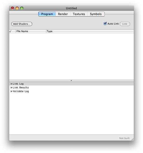
The top part of the view is used for listing source code filenames. You can add files in any of these ways:
Drag previously created files to the window.
Use the Add Shaders button to navigate and choose previously created files.
Choose File > New > to create a new file for a GLSL program (vertex, fragment, geometry) or an ARB program (vertex, fragment).
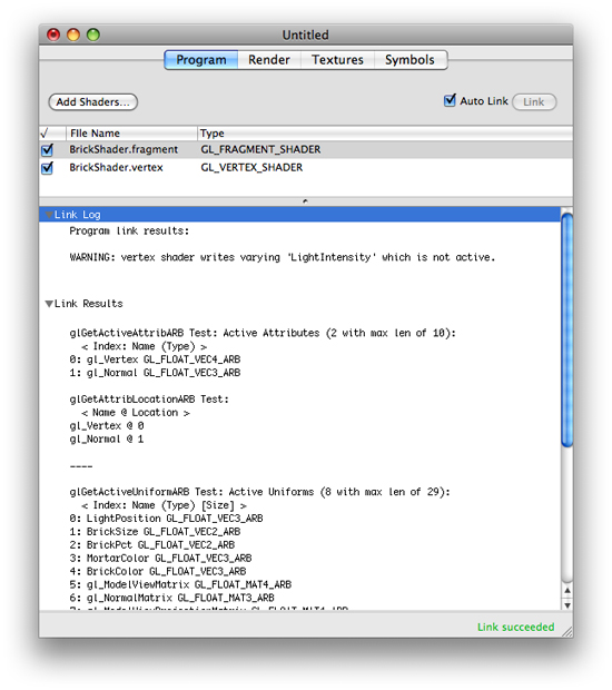
Figure 1-2 shows the Program view after you’ve adding fragment and vertex source code files. The link log, link results, and validation log appear below the file list. The link status, which in this case is “Link succeeded,” appears in the lower-right corner of the window.
Source Code Files
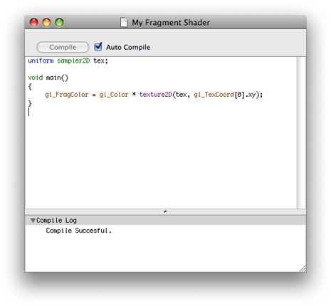
You can view and modify the contents of each source code file by double-clicking its name in the file list. The file opens in a new window, as shown in Figure 1-3. When you create a new source code file, it opens automatically in a new document window. In contrast, new source code files open in a new document window automatically. These new source code files contain template code that you can modify or replace to suit your needs.
Controls for Geometry Shaders
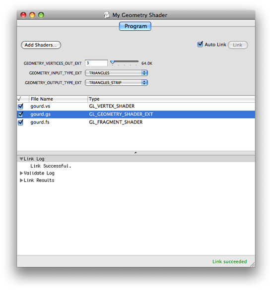
A geometry shader object is made up of a geometry program and a vertex program. When you add the geometry source code file to the program list, the user interface changes (see Figure 1-4) to show controls for the following OpenGL parameters, which the GL_NV_geometry_shader4 extension defines:
GEOMETRY_VERTICES_OUT_EXTis the maximum number of vertices produced by the geometry shader.GEOMETRY_INPUT_TYPE_EXTis the geometry that the shader takes as input:POINTS,LINES,LINES_ADJACENCY_EXT,TRIANGLES, orTRIANGLES_ADJACENCY_EXT.GEOMETRY_OUTPUT_TYPE_EXTis the geometry that the shader produces:POINTS,LINE_STRIP, orTRIANGLE_STRIP.
Render View
The Render view, shown in Figure 1-5, visualizes what your code does. Although you can click the Render tab to switch between the Program and Render views, it’s more efficient to double-click the Render tab to open the view in a separate Render window. That way, you can look at the rendering results side-by-side with the contents of the Program, Textures, and Symbols views.
For details on customizing the layout of windows, see Creating and Saving a Layout.
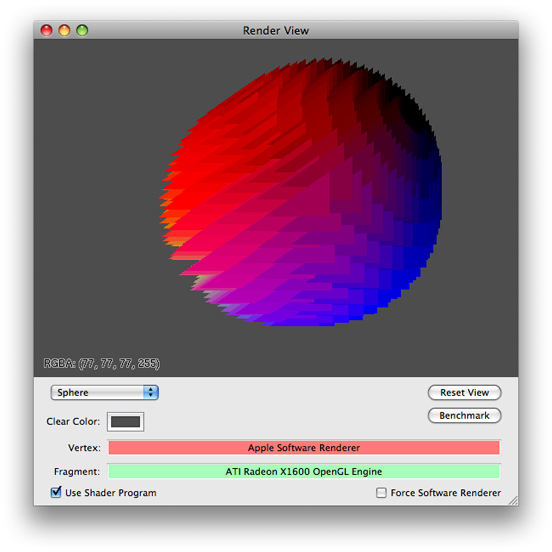
The pop-up menu lets you choose from among several geometries—Teapot Wire, Teapot Point, Plane, Teapot, Squiggle, Sphere, or Torus—to apply your code to. You can interact with any of the 3D geometries by clicking and dragging the pointer.
Textures View
The Textures view, shown in Figure 1-6, lets you add and set up textures to use as input to fragment programs. To add a texture, you simply drag it to one of the image wells on the right side of the view. When you select an image well, the texture appears on the left side of the view.
After selecting a texture, you can adjust any of the following by choosing the appropriate OpenGL constant from the provided pop-up menus:
Texture types:
1D,2D,Rectangle,3D,Cube_MAP,SHADOW_1D,SHADOW_2D, orSHADOW_RECTANGLEMethods of filtering:
NEAREST,LINEAR,NEAREST_MIPMAP_NEAREST,LINEAR_MIPMAP_NEAREST,NEAREST_MIPMAP_LINEAR, orLINEAR_MIPMAP_LINEARWrapping modes:
REPEAT,CLAMP,CLAMP_TO_EDGE,CLAMP_TO_BORDER, orMIRRORED_REPEAT
When you change the texture type, filter, or wrapping mode, you get immediate feedback on the effect. As a result, you’ll be able to compare filtering methods and wrapping modes easily.
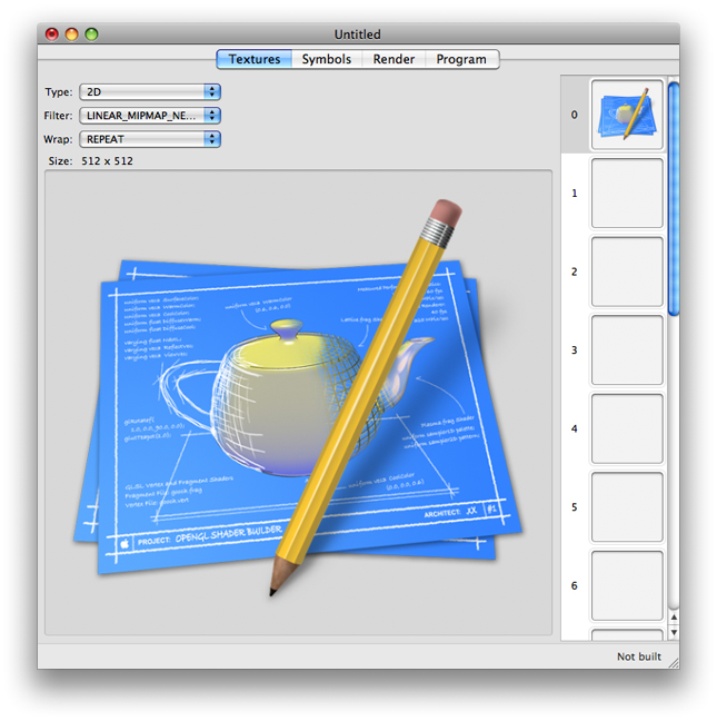
You can get an idea of how OpenGL maps a texture to an object by looking an an alternate view of the texture. To see an alternate view, double-click the texture that appears in the view on the left. The default view is a flat representation of the texture without the wrapping mode. The alternate view maps the texture in the dimension of its type (1D, 2D, 3D, Cube) and applies the filtering and wrapping modes.
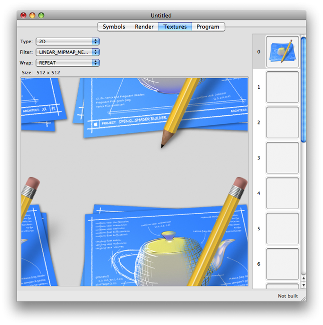
Figure 1-7 is the alternate view for the texture shown in Figure 1-6. This view shows the repeating pattern caused by choosing the REPEAT wrapping mode.
For more details on working with textures, see Adding Textures and Using Alternate Texture Views.
Symbols View
After you add shaders to the Program view, you can view its uniform variables in the Symbols view, as shown in Figure 1-8. You can modify and animate GLSL uniform variables and ARB environment and local parameters.
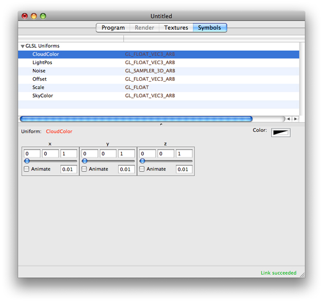
For more information, see Modifying Uniform Variables.
Copyright © 2015 Apple Inc. All Rights Reserved. Terms of Use | Privacy Policy | Updated: 2015-03-09