64-bit PowerPC Function Calling Conventions
When functions (routines) call other functions (subroutines), they may need to pass arguments to them. These subroutines access those arguments as parameters. Conversely, some functions pass a result or return value to their callers. Both arguments and results can be passed using the 64-bit PowerPC architecture registers or the runtime stack, depending on the data type of the values involved. For the successful and efficient passing of values between routines and subroutines, GCC follows strict rules when it generates a program’s object code.
This article describes the data types that can be used to manipulate the arguments and results of function calls, how routines pass arguments to the subroutines they call, and how functions pass results to their callers. It also lists the registers available in the 64-bit PowerPC architecture and whether their value is preserved after a function call.
Data Types and Data Alignment
Using the correct data types for your variables and setting the appropriate data alignment for your data can maximize the performance and portability of your programs. Data alignment specifies how data is laid out in memory.
Table 1 lists the ANSI C scalar data types and their sizes and natural alignment in this environment.
Data type | Size and natural alignment (in bytes) |
|---|---|
| 1 |
| 1 |
| 1 |
| 2 |
| 2 |
| 4 |
| 4 |
| 8 |
| 8 |
| 8 |
| 8 |
| 4 |
| 8 |
| 16 |
pointer | 8 |
These are some important details about the 64-bit PowerPC environment:
This environment uses the big-endian byte ordering scheme to store numeric and pointer data types. That is, the most significant bytes go first, followed by the least significant bytes.
This environment uses the two’s-complement binary representation for signed integer data types.
The
floatanddoubledata types conform to the IEEE-754 standard representation. For the value range and precise format of floating-point data types, see PowerPC Numerics in Performance Documentation.
This environment supports multiple data alignment modes. Alignment of data types falls into two categories:
Natural alignment. The alignment of a data type when allocated in memory or assigned a memory address.
The natural alignment of a data type is its size. Table 1 shows the natural alignment of each data type supported by this environment.
Embedding alignment. The alignment of a data type within a composite data structure.
For example, the alignment of an unsigned short variable on the stack may differ from that of an unsigned short data item embedded in a data structure.
The embedding alignment for data structures varies depending on the alignment mode selected. Generally, you can set the alignment mode using compiler options or #pragma statements. You should consider the compatibility and performance issues described later in this section when choosing a particular alignment mode.
These are the embedding alignment modes available in the 64-bit PowerPC environment:
Power alignment mode is derived from the alignment rules used by the IBM XLC compiler for the AIX operating system. It is the default alignment mode for the PowerPC-architecture version of GCC used on AIX and OS X. Because this mode is most likely to be compatible between PowerPC-architecture compilers from different vendors, it’s typically used with data structures that are shared between different programs.
The rules for power alignment are:
The embedding alignment of the first element in a data structure is equal to the element’s natural alignment.
For subsequent elements with a natural alignment less than 4 bytes, the embedding alignment of each element is equal to its natural alignment.
For subsequent elements that have a natural alignment greater than 4 bytes, the embedding alignment is 4, unless the element is a
vector.The embedding alignment for
vectorelements is always 16 bytes.The embedding alignment of a composite data type (array or data structure) is determined by the largest embedding alignment of its members.
The total size of a composite type is rounded up to a multiple of its embedding alignment, and is padded with null bytes.
Because the natural alignment of
doubleandlong longdata types is greater than 4 bytes, they may not be appropriately aligned in power-alignment mode. Any misalignment impairs performance when such data members are accessed. When you use these data types for any element after the first element, the compiler pads the structure to align the elements to their natural alignment.Natural alignment mode uses the natural alignment of each data type as its embedding alignment. Use this alignment mode to obtain the highest performance when using
double,long,long long, andlong doubledata types.Packed alignment mode contains no alignment padding between elements (the alignment for all data types is 1 byte). Use this alignment mode when you need a data structure to use as little memory as possible. Note, however, that packed alignment can significantly lower the performance of your application.
Table 2 lists the alignment for structure fields of the fundamental data types and composite data types in the supported alignment modes.
Data type | Natural alignment | Power alignment | Packed alignment |
|---|---|---|---|
| 1 | 1 | 1 |
| 1 | 1 | 1 |
| 2 | 2 | 1 |
| 4 | 4 | 1 |
| 8 | 4 | 1 |
| 8 | 4 | 1 |
| 4 | 4 | 1 |
| 8 | 4 or 8 | 1 |
| 8 | 8 | 1 |
| 16 | 16 | 1 |
Composite (data structure or array) | 1, 2, 4, 8, or 16 | 4, 8, or 16 | 1 |
With GCC you can control data-structure alignment by adding #pragma statements to your source code or by using command-line options. The power alignment mode is used if you do not specify otherwise.
To set the alignment mode, use the gcc flags -malign-power and -malign-natural. To use a specific alignment mode in a data structure, add this statement just before the data-structure declaration:
#pragma option align=<mode> |
Replace <mode> with power, natural, or packed. To restore the previous alignment mode, use reset as the alignment mode in a #pragma statement:
#pragma option align=reset |
Function Calls
This section details the process of calling a subroutine and passing arguments to it, and how functions return values to their callers.
Stack Structure
This environment uses a stack that grows downward and contains linkage information, local variables, and a subroutine’s parameter information, as shown in Figure 1. (To help prevent the execution of malicious code on the stack, GCC protects the stack against execution.)
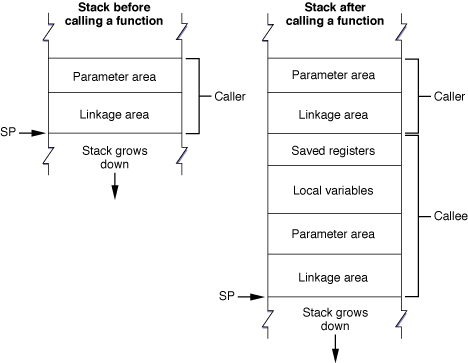
The stack pointer (SP) points to the bottom of the stack. The stack has a fixed frame size, which is known at compile time.
The calling routine’s stack frame includes a parameter area and some linkage information. The parameter area has the arguments the caller passes to the called subroutine or space for them, depending on the type of each parameter and the availability of registers (see Passing Arguments for details). Since the calling routine may call several subroutines, the parameter area must be large enough to accommodate the largest argument list of all the subroutines the caller calls. It is the calling routine’s responsibility to set up the parameter area before each function call. The called function is responsible for accessing the arguments placed in the parameter area.
Bytes 48 through 112 of the parameter area correspond to the general-purpose registers GPR3 through GPR10. When data is placed in a general-purpose register and not duplicated in the parameter area, the corresponding section in the parameter area is reserved in case the called subroutine needs to copy the value in the register to the stack. Table 3 shows the correspondence of parameter-area locations to the general-purpose registers that can be used to pass parameters.
Stack frame location | Register |
|---|---|
| GPR3 |
| GPR4 |
| GPR5 |
| GPR6 |
| GPR7 |
| GPR8 |
| GPR9 |
| GPR10 |
When space is allocated for a parameter in the parameter area, the space allocated may be larger than the parameter’s type. In this case, the parameter is “promoted” to a larger data type. Each parameter’s address is the address of the previous parameter plus the size of the previous parameter’s promoted type.
These are the promotion and alignment rules followed when parameters are placed in the parameter area or in general-purpose registers:
Integers are promoted to
long. For example,shortelements are sign-extended to 64-bits, andunsigned intelements are zero-padded on the left to 64-bits.Composite arguments (arrays and structures) are processed this way:
The aligned size is computed by adding necessary padding to make it a multiple of the alignment.
If the aligned size is 1, 2 or 4, the argument is preceded by padding to 4 bytes.
Otherwise, the argument is followed by padding to make its size a multiple of 4 bytes, with the padding bytes being undefined. (GCC pads with
0.
Parameters with a 16-byte natural alignment (for example, vectors or structures containing a vector), are 16-byte aligned.
For example, assume the function foo is declared like this:
int foo(int i, float f, long l, vector int v, |
double d, void* p, char c, short s); |
The layout of the parameter area would be as shown in Table 4.
Parameter | Declared type | Promoted type | Location |
|---|---|---|---|
|
|
|
|
|
|
|
|
|
|
|
|
|
|
|
|
|
|
|
|
|
|
|
|
|
|
|
|
|
|
|
|
The calling routine’s linkage area holds a number of values, some of which are saved by the calling routine and some by the called subroutine. The elements within the linkage area are:
The link register (LR). It’s value is saved at
16(SP)by the called function if it chooses to do so. The link register holds the return address of the instruction that follows a branch and link instruction.The condition register (CR). It’s value may be saved at
8(SP)by the called function. The condition register holds the results of comparison operations. As with the link register, the called subroutine is not required to save this value. Because the condition register is a 32-bit register, bytes 12 through 15 of the stack frame are unused but reserved.The stack pointer (SP). It’s value may be saved at
0(SP)by the called function as part of its stack frame. Leaf subroutines are not required to save the the stack pointer. A leaf function is a routine that does not call any other function.
The linkage area is at the top of the stack frame, adjacent to the stack pointer. This positioning is necessary so the calling routine can find and restore the values stored there and also allow the called subroutine to find the caller’s parameter area. This placement means that a routine cannot push and pop parameters from the stack once the stack frame is set up.
The stack frame also includes space for the called function’s local variables. However, some registers are available for use by the called function; see Register Preservation for details. If the subroutine contains more local variables than would fit in the registers, it uses additional space on the stack. The size of the local-variable area is determined at compile time. Once a stack frame is allocated, the size of the local-variable area cannot change.
Prologs and Epilogs
The called function is responsible for allocating its own stack frame, making sure to preserve 16-byte alignment in the stack. This operation is accomplished by a section of code called the prolog, which the compiler places before the body of the subroutine. After the body of the subroutine, the compiler places an epilog to restore the processor to the state it was prior to the subroutine call.
The compiler-generated prolog code does the following:
Decrements the stack pointer to account for the new stack frame and writes the previous value of the stack pointer into its own linkage area, which ensures the stack can be restored to its original state after returning from the call.
It is important that the decrement and update tasks happen atomically (for example, with
stwu,stwux,stdu, orstdux) so that the stack pointer and back-link are in a consistent state. Otherwise, asynchronous signals or interrupts could corrupt the stack.Saves all nonvolatile general-purpose and floating-point registers into the saved-registers area. Note that if the called function does not change a particular nonvolatile register, it does not save it.
Saves the link-register and condition-register values in the caller’s linkage area, if needed.
Listing 1 shows an example of a routine prolog. Notice that the order of these actions differs from the order previously described.
Listing 1 Example prolog
linkageArea = 48 ; size in 64-bit PowerPC ABI |
params = 64 ; callee parameter area |
localVars = 0 ; callee local variables |
numGPRs = 0 ; volatile GPRs used by callee |
numFPRs = 0 ; volatile FPRs used by callee |
spaceToSave = linkageArea + params + localVars + 8*numGPRs + 8*numFPRs |
spaceToSaveAligned = ((spaceToSave+15) & (-16)) ; 16-byte-aligned stack |
_functionName: ; PROLOG |
mflr r0 ; extract return address |
std r0, 16(SP) ; save the return address |
stdu SP, -spaceToSaveAligned(SP) ; skip over caller save area |
At the end of the function, the compiler-generated epilog does the following:
Restores the nonvolatile general-purpose and floating-point registers that were saved in the stack frame.
Nonvolatile registers are saved in the new stack frame before the stack pointer is updated only when they fit within the space beneath the stack pointer, where a new stack frame would normally be allocated, also known as the red zone. The red zone is by definition large enough to hold all nonvolatile general-purpose and floating-point registers but not the nonvolatile vector registers. See The Red Zone for details.
Restores the condition-register and link-register values that were stored in the linkage area.
Returns control to the calling routine using the address stored in the link register.
Listing 2 shows an example epilog.
Listing 2 Example epilog
; EPILOG |
ld r0, spaceToSaveAligned + 16(SP) ; get the return address |
mtlr r0 ; into the link register |
addi SP, SP, spaceToSaveAligned ; restore stack pointer |
blr ; and branch to the return address |
The VRSAVE register is used to specify which vector registers must be saved during a thread or process context switch.Listing 3 shows an example prolog that sets up VRSAVE so that vector registers V0 through V2 are saved. Listing 3 also includes the epilog that restores VRSAVE to its previous state.
Listing 3 Example usage of the VRSAVE register
#define VRSAVE 256 // VRSAVE IS SPR# 256 |
_functionName: |
mfspr r2, VRSAVE ; get vector of live VRs |
oris r0, r2, 0xE000 ; set bits 0-2 since we use V0..V2 |
mtspr VRSAVE, r0 ; update live VR vector before using any VRs |
; Now, V0..V2 can be safely used. |
; Function body goes here. |
mtspr VRSAVE, r2 ; restore VRSAVE |
blr ; return to caller |
The Red Zone
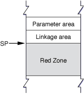
The space beneath the stack pointer, where a new stack frame would normally be allocated by a subroutine, is called the red zone. The red zone, shown in Figure 2, is considered part of the topmost (current) stack frame. This area is not modified by asynchronous pushes, such as signals or interrupt handlers. Therefore, the red zone may be used for any purpose as long as a new stack frame does not need to be added to the stack. However, the contents of the red zone are assumed to be destroyed by any synchronous call.
For example, because a leaf function does not call any other functions—and, therefore, does not allocate a parameter area on the stack—it can use the red zone. Furthermore, such a function does not need to use the stack to store local variables; it needs to save only the nonvolatile registers that it uses for local variables. Since by definition no more than one leaf function is active at any time within a thread, there is no possibility of multiple leaf functions competing for the same red zone space.
A leaf function may or may not allocate a stack frame and decrement the stack pointer. When it doesn’t allocate a stack frame, a leaf function stores the link register and condition register values in the linkage area of the routine that calls it (if necessary) and stores the values of any nonvolatile registers it uses in the red zone. This streamlining means that a leaf function’s prolog and epilog do minimal work; they do not have to set up and take down a stack frame.
The size of the red zone is 288 bytes, which is enough space to store the values of nineteen 64-bit general-purpose registers and eighteen 64-bit floating-point registers, rounded up to the nearest 16-byte boundary. If a leaf function’s red zone usage would exceed the red zone size, it must set up a stack frame, just as functions that call other functions do.
Passing Arguments
In the C language, functions can declare their parameters using one of three conventions:
The types of all parameters is specified in the function’s prototype. For example:
int foo(int, short);
In this case, the type of all the function’s parameters is known at compile time.
The function’s prototype declares some fixed parameters and some nonfixed parameters. The group of nonfixed parameters is also called a variable argument list. For example:
int foo(int, ...);
In this case, the type of one of the function’s parameters in known at compile time. The type of the nonfixed parameters is not known.
The function has no prototype or uses a pre–ANSI C declaration. For example:
int foo();
In this case, the type of all the function’s parameters is unknown at compile time.
When the compiler generates the prolog for a function call, it uses the information from the function’s declaration to decide how to pass arguments to the function. When the compiler knows the type of a parameter, it passes it in the most efficient way possible. But when the type is unknown, it passes the parameter using the safest approach, which may involve placing data both in registers and in the parameter area. For called functions to access their parameters correctly, it’s important that they know when parameters are passed in the stack or in registers.
Arguments are passed in the stack or in registers depending on their types and the availability of registers. There are three types of registers: general purpose, floating point, and vector. General-purpose registers (GPRs) are 64-bit registers that can manipulate integral values and pointers. Floating-point registers (FPRs) are 64-bit registers that can manipulate single-precision and double-precision floating-point values. Vector registers are 128-bit registers that can manipulate 4 through 16 chunks of data in parallel.
The registers that can be used to pass arguments to called functions are the general-purpose registers GPR3 through GPR10, the floating-point registers FPR1 through FPR13, and the vector registers V2 through V13 (see Register Preservation for details). These registers are also known as parameter registers.
The compiler uses the following rules when passing arguments to subroutines:
Parameters whose promoted type is known at compile time are processed using these rules (see Stack Structure for details on a parameter’s promoted type):
The caller places floating-point elements (except
long doubleelements) in floating-point registers FPR1 through FPR13. As each floating-point register is used, the caller skips the next available general-purpose register. When floating-point registers are exhausted, the caller places these elements in the parameter area.The caller places
long doubleelements—which use a pair offloatelements—in two floating-point registers. As each pair of floating-point registers is used, the caller skips the next two available general-purpose registers. When floating-point registers are exhausted, the caller places these elements in the parameter area.The caller places
vectorelements in vector registers V2 through V13. Vector-register usage doesn’t affect the availability of general-purpose registers. That is, no general-purpose registers are skipped as a result of using a vector register. When vector registers are exhausted, the caller places these elements in the parameter area.The caller places elements of all other data types—including
complex(defined incomplex.h)—in general-purpose registers GPR3 through GPR10, when available. When general-purpose registers are exhausted, the caller places these elements in the parameter area.Structures that are 16 bytes in size are handled as if they were a pair of 64-bit integers. Therefore, they are placed in two general-purpose registers. Examples of structures that meet this criterion include a structure containing four
floatfields and a structure containing twodoublefields. Structures that contain threefloatfields, for example, are be processed using rule 5.The caller recursively processes the members of structures passed by value and containing no unions:
Arguments to a pre–ANSI C–declared function are processed as follows:
The caller places floating-point elements in floating-point registers and general-purpose registers, when available. Otherwise, the caller places them in the parameter area.
The caller places
vectorelements in vector registers and general-purpose registers, when available. Otherwise, the caller places them in the parameter area.The caller places elements of all other types in general-purpose registers, when available. Otherwise, the caller places them in the parameter area.
Arguments that are part of a variable argument list are placed in general-purpose registers, when available. Otherwise, the caller places them in the parameter area.
Using ANSI C Prototypes
When the types of all the parameters of a subroutine are known at compile time, placing arguments into registers is straightforward.
For example, assume a routine calls the function foo_ansi declared like this:
int foo_ansi(int i, float f, long l, vector int v, |
double d, void* p, char c, short s); |
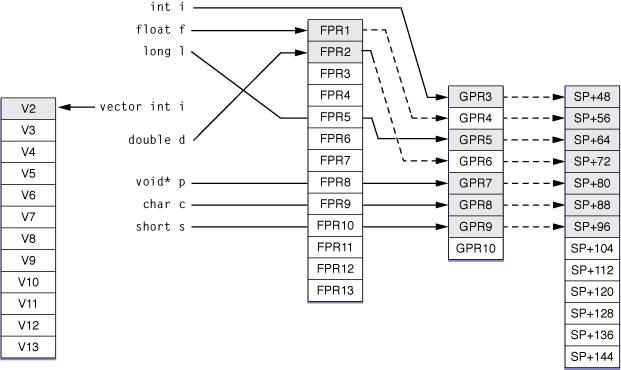
The caller places the arguments to the function as shown in Table 5.
Argument | Type | Placed in | Reason |
|---|---|---|---|
i |
| GPR3 | Not a floating-point or vector element. |
f |
| FPR1 | First floating-point element, so it goes in the first floating-point register. GPR4 is skipped. |
l |
| GPR5 | Not a floating-point or vector element. |
v |
| V2 | First vector element, so it goes in the first vector register. No general-purpose register is skipped. |
d |
| FPR2 | Second floating-point element, so it goes in the next floating-point register available. GPR6 is skipped. |
p |
| GPR7 | Not a floating-point or vector element. |
c |
| GPR8 | Not a floating-point or vector element. |
s |
| GPR9 | Not a floating-point or vector element. |
Figure 3 illustrates the placement of arguments in registers and the parameter area.
Using Structures
Assume the structure data and the function bar are declared like this:
struct data { |
float f; |
int i; |
double d; |
vector float v; |
}; |
int bar(int a, struct data b, void* c); |
Table 6 shows the register assignment when a routine calls bar.
Argument | Type | Placed in | Reason |
|---|---|---|---|
|
| GPR3 | Not a floating-point or vector element. |
|
| FPR1 | First floating-point element, so it goes in the first floating-point register. GPR4 is skipped. Because the |
|
| GPR5 (low half) | Not a floating-point or vector element. |
|
| FPR2 | Second floating-point element, so it goes in the next floating-point register available. |
|
| V2 | First vector element, so it goes in the first vector register. |
|
| GPR9 | Not a floating-point or vector element. |
Using Variable Argument Lists
Assume the structure numbers and the function var are declared like this:
struct numbers { |
float f; |
int i; |
}; |
extern void var(int a, float b, vector float c, struct numbers n, ...); |
Also assume a routine contains the following code:
int i1, i2; |
float f1, f2; |
vector float v1, v2; |
struct numbers n1, n2; |
... |
var(i1, f1, v1, n1, i2, f2, v2, n2); |
The caller assigns the arguments to var as shown in Table 7.
Argument | Type | Placed in | Reason |
|---|---|---|---|
|
| GPR3 | Not a floating-point or vector element. |
|
| FPR1 | First floating-point element, so it goes in the first floating-point register. |
|
| V2 | First vector element, so it goes in the first vector register. |
|
| FPR2 | Second floating-point element, so it goes in the next floating-point register available. |
|
| GPR7 (low half) | Not a floating-point or vector element. |
|
| GPR8 | A variable argument list element. |
|
| GPR9 | A variable argument list element. |
|
|
| A variable argument list element and a vector. Must be 16-byte aligned; cannot use GPR10. |
|
|
| A variable argument list element. No general-purpose registers available. |
|
|
| A variable argument list element. No general-purpose registers available. |
Using pre–ANSI C Prototypes
Assume the structure numbers and the function foo_pre_ansi are declared like this:
struct numbers { |
float f; |
int i; |
}; |
void foo_pre_ansi(); |
Also assume a routine contains the following code:
... |
int i; |
float f; |
vector float v; |
struct numbers n; |
... |
foo_pre_ansi(i, f, v, n); |
The caller assigns the arguments to foo_pre_ansi as shown in Table 8.
Argument | Type | Placed in | Reason |
|---|---|---|---|
|
| GPR3 | Not a floating-point or vector element. |
|
| FPR1, GPR4 | First floating-point element, so it goes in the first floating-point register and the next available general-purpose register. |
|
| V2, GPR5–GPR6 | First vector element, so it goes in the first vector register and next two general-purpose registers available. |
|
| FPR2, GPR7 (high half) | Second floating-point element, so it goes in the next floating-point register available and the next general-purpose register available. |
|
| GPR7 (low half) | Not a floating-point or vector element, so it goes in the next general-purpose register available. |
Returning Results
A function result can be returned in registers or in memory, depending on the data type of the function’s return value. When the return value of the called function would be passed in registers, if it were passed as a parameter in a function call, the called function places its return value in the same registers. Otherwise, the function places its result at the location pointed to by GPR3. See Passing Arguments for more information.
Table 9 lists some examples of how return values can be passed to a calling routine.
Return type | Returned in |
|---|---|
| GPR3 (sign extended). |
| GPR3 (zero filled). |
| GPR3. |
| GPR3. |
| FPR1. |
| FPR1. |
| FPR1–FPR2. |
| FPR1, FPR2. |
| FPR1, FPR2. |
| GPR3, GPR4. |
| GPR3, GPR4, ... GPR10. |
| Memory location pointed to by GPR3, which is made up of 80 bytes of storage. |
| V2. |
| FPR1 (real number), FPR2 (imaginary number). |
| FPR1 (real number), FPR2 (imaginary number). |
| FPR1–FPR2 (real number), FPR3–FPR4 (imaginary number). |
Register Preservation
Table 10 lists the 64-bit PowerPC architecture registers used in this environment and their volatility in subroutine calls. Registers that must preserve their value after a function call are called nonvolatile.
Type | Name | Preserved | Notes |
|---|---|---|---|
General-purpose register | GPR0 | No | |
GPR1 | Yes | Used as the stack pointer to store parameters and other temporary data items. | |
GPR2 | No | Available for general use. | |
GPR3 | No | The caller passes arguments to the called subroutine in GPR3 through GPR10. The caller may also pass the address to storage where the callee places its return value in this register. | |
GPR4–GPR10 | No | Used by callers to pass arguments to the called subroutine (see notes for GPR3). | |
GPR11 | Yes in nested functions. No in leaf functions. | In nested functions, the caller passes its stack frame to the nested function in this register. In leaf subroutines, the register is available. For details on nested functions, see the GCC documentation. This register is also used by lazy stubs in dynamic code generation to point to the lazy pointer. | |
GPR12 | No | Set to the address of the branch target before an indirect call for dynamic code generation. This register is not set for a subroutine that has been called directly, so subroutines that may be called directly should not depend on this register being set up correctly. See Mach-O Programming Topics for more information. | |
GPR13 | Yes | Reserved for thread-specific storage. | |
GPR14–GPR31 | Yes | ||
Floating-point register | FPR0 | No | |
FPR1–FPR13 | No | Used by callers to pass floating-point arguments to the called subroutine. Floating-point results are passed in FPR1. | |
FPR14–FPR31 | Yes | ||
Vector register | V0–V19 | No | Callers use V2 through V13 to pass vector arguments to the called subroutine. Vector results are passed in V2. |
V20–V31 | Yes | ||
Special-purpose vector register | VRSAVE | Yes | 32-bit special-purpose register. Each bit in this register indicates whether the corresponding vector register must be saved during a thread or process context switch. |
Link register | LR | No | Stores the return address of the calling routine that called the current subroutine. |
Count register | CTR | No | |
Fixed-point exception register | XER | No | |
Condition register fields | CR0, CR1 | No | |
CR2–CR4 | Yes | ||
CR5–CR7 | No |
Copyright © 2010 Apple Inc. All Rights Reserved. Terms of Use | Privacy Policy | Updated: 2010-11-17