Retired Document
Important: This document is retired because the content has been migrated to SpriteKit reference.
Building Your Scene
You have already learned many things about working with scenes. Here’s a quick recap of the important facts:
Scenes (
SKSceneobjects) are used to provide content to be rendered by anSKViewobject.A scene’s content is created as a tree of node objects. The scene is the root node.
When presented by a view, a scene runs actions and simulates physics, then renders the node tree.
You create custom scenes by subclassing the
SKSceneclass.
With those basic concepts in mind, it is time to learn more about the node tree and building your scenes.
A Node Provides a Coordinate System to Its Children
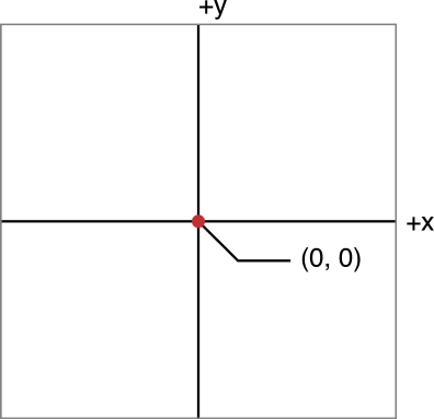
When a node is placed in the node tree, its position property places it within a coordinate system provided by its parent. SpriteKit uses the same coordinate system on both iOS and OS X. Figure 4-1 shows the SpriteKit coordinate system. Coordinate values are measured in points, as in UIKit or AppKit; where necessary, points are converted to pixels when the scene is rendered. A positive x coordinate goes to the right and a positive y coordinate goes up the screen.
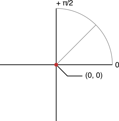
SpriteKit also has a standard rotation convention. Figure 4-2 shows the polar coordinate convention. An angle of 0 radians specifies the positive x axis. A positive angle is in the counterclockwise direction.
When you are working only with SpriteKit code, a consistent coordinate system means that you can easily share code between an iOS and OS X version of your game. However, it does mean that when you write OS-specific user interface code, you may need to convert between the operating system’s view coordinate conventions and SpriteKit’s coordinate system. This is most often the case when working with iOS views, which use a different coordinate convention.
Only Some Nodes Contain Content
Not all nodes draw content. For example, the SKSpriteNode class draws a sprite, but the SKNode class doesn’t draw anything. You can tell whether a particular node object draws content by reading its frame property. The frame is the visible area of the parent’s coordinate system that the node draws into. If the node draws content, this frame has a nonzero size. For a scene, the frame always reflects the visible portion of the scene’s coordinate space.
If a node has descendants that draw content, it is possible for a node’s subtree to provide content even though it doesn’t provide any content itself. You can call a node’s calculateAccumulatedFrame method to retrieve a rectangle that includes the entire area that a node and all of its descendants draw into.
Creating a Scene
A scene is presented by a view. The scene includes properties that define where the scene’s origin is positioned and the size of the scene. If the scene does not match the view’s size, you can also define how the scene is scaled to fit in the view.
A Scene’s Size Defines Its Visible Area
When a scene is first initialized, its size property is configured by the designated initializer. The size of the scene specifies the size of the visible portion of the scene in points. This is only used to specify the visible portion of the scene. Nodes in the tree can be positioned outside of this area; those nodes are still processed by the scene, but are ignored by the renderer.
Using the Anchor Point to Position the Scene’s Coordinate System in the View
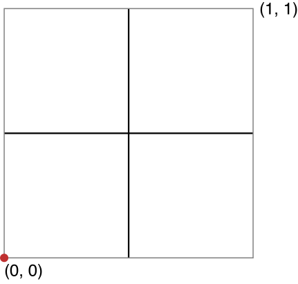
By default, a scene’s origin is placed in the lower-left corner of the view, as shown in Figure 4-3. So, a scene is initialized with a height of 1024 and a width of 768, has the origin (0,0) in the lower-left corner, and the (1024,768) coordinate in the upper-right corner. The frame property holds (0,0)-(1024,768).
A scene’s position property is ignored by Scene Kit because the scene is always the root node for a node tree. Its default value is CGPointZero and you can’t change it. However, you can move the scene’s origin by setting its anchorPoint property. The anchor point is specified in the unit coordinate space and chooses a point in the enclosing view.
The default value for the anchor point is CGPointZero, which places it at the lower-left corner. The scene’s visible coordinate space is (0,0) to (width,height). The default anchor point is most useful for games that do not scroll a scene’s content.
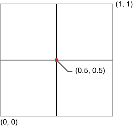
The second-most common anchor point value is (0.5,0.5), which centers the scene’s origin in the middle of the view as shown in Figure 4-4. The scene’s visible coordinate space is (-width/2,-height/2) to (width/2, height/2). Centering the scene on its anchor point is most useful when you want to easily position nodes relative to the center of the screen, such as in a scrolling game.
So, to summarize, the anchorPoint and size properties are used to compute the scene’s frame, which holds the visible portion of the scene.
A Scene’s Contents Are Scaled to Fit the View
After a scene is rendered, its contents are copied into the presenting view. If the view and the scene are the same size, then the content can be directly copied into the view. If the two differ, then the scene is scaled to fit in the view. The scaleMode property determines how the content is scaled.
When you design your game, you should decide on a strategy for handling the scene’s size and scaleMode properties. Here are the most common strategies:
Instantiate the scene with a constant size and never change it. Pick a scaling mode that lets the view scale the scene’s content. This gives the scene a predictable coordinate system and frame. You can then base your art assets and gameplay logic on this coordinate system.
Adjust the size of the scene in your game. Where necessary, adjust your game logic and art assets to match the scene’s size.
Set the
scaleModeproperty toSKSceneScaleModeResizeFill. SpriteKit automatically resizes the scene so that it always matches the view’s size. Where necessary, adjust your game logic and art assets to match the scene’s size.
Listing 4-1 shows a typical implementation for when you plan to use a constant-sized scene. As with the example you created in Jumping into SpriteKit, this code specifies a method to be executed the first time that the scene is presented. It configures the scene’s properties, including its scaling mode, then adds content. In this example, the scale mode is set to SKSceneScaleModeAspectFit, which scales the contents equally in both dimensions and ensures that all of the scene’s contents are visible. Where necessary, this mode adds letterboxing.
Listing 4-1 Using the scale mode for a fixed-size scene
- (void)createSceneContent |
{ |
self.scaleMode = SKSceneScaleModeAspectFit; |
self.backgroundColor = [SKColor blackColor]; |
// Add additional scene contents here. |
... |
} |
If you expect a scene’s size to change at runtime, then the initial scene size should be used to determine which art assets to use, as well as any game logic that is dependent on the scene size. Your game should also override the scene’s didChangeSize: method, which is called whenever the scene changes size. When this method is called, you should update the scene’s contents to match the new size.
Creating the Node Tree
You create the node tree by creating parent-child relationships between nodes. Each node maintains an ordered list of children, referenced by reading the node’s children property. The order of the children in the tree affects many aspects of scene processing, including hit testing and rendering. So, it is important to organize the node tree appropriately.
Table 4-1 lists the most common methods used to build the node tree. The complete list of methods is provided in SKNode Class Reference.
Method | Description |
|---|---|
Adds a node to the end of the receiver’s list of child nodes. | |
Inserts a child into a specific position in the receiver’s list of child nodes. | |
Removes the receiving node from its parent. |
When you need to directly transverse the node tree, you use the properties in Table 4-2 to uncover the tree’s structure.
Property | Description |
|---|---|
The array of | |
If the node is a child of another node, this holds the parent. Otherwise, it holds | |
If the node is included anywhere in a scene, this returns the scene node that is the root of the tree. Otherwise it holds |
Understanding the Drawing Order for a Node Tree
The standard behavior for scene rendering follows a simple pair of rules:
A parent draws its content before rendering its children.
Children are rendered in the order in which they appear in the child array.
Figure 4-5 shows how a node with four children are rendered.
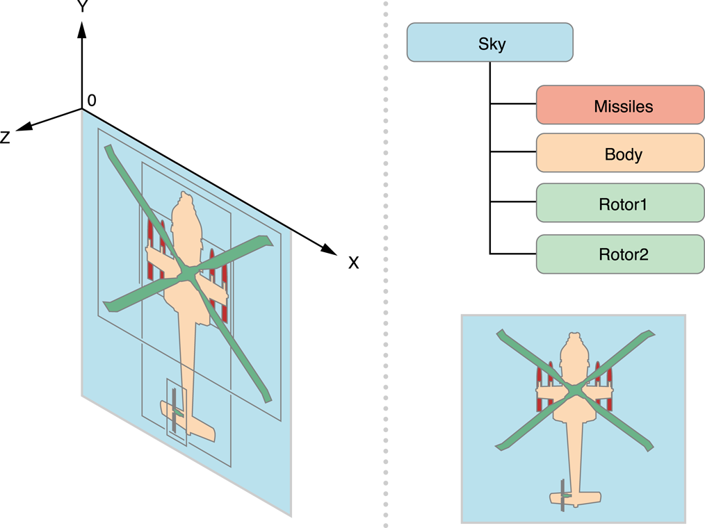
In the code you wrote in Jumping into SpriteKit, you created a scene with a spaceship and rocks. Two lights were specified as children of the spaceship, and the spaceship and rocks were the scene’s children. So the scene rendered its content as follows:
The scene renders itself, clearing its contents to its background color.
The scene renders the spaceship node.
The spaceship node renders its children, which are the lights on the spaceship.
The scene renders the rock nodes, which appear after the spaceship node in the scene’s array of children.
Maintaining the order of a node’s children can be a lot of work. Instead, you can give each node an explicit height in the scene. You do this by setting a node’s zPosition property. The z position is the node’s height relative to its parent node, much as a node’s position property represents its x and y position relative to parent’s position. So you use the z position to place a node above or below the parent’s position.
When you take z positions into account, here is how the node tree is rendered:
Each node’s global z position is calculated.
Nodes are drawn in order from smallest z value to largest z value.
If two nodes share the same z value, ancestors are rendered first, and siblings are rendered in child order.
As you’ve just seen, SpriteKit uses a deterministic rendering order based on the height nodes and their positions in the node tree. But, because the rendering order is so deterministic, SpriteKit may be unable to apply some rendering optimizations that it might otherwise apply. For example, it might be better if SpriteKit could gather all of the nodes that share the same texture and drawing mode and and draw them with a single drawing pass. To enable these sorts of optimizations, you set the view’s ignoresSiblingOrder property to YES.
When you ignore sibling order, SpriteKit uses the graphics hardware to render the nodes so that they appear sorted by z order. It sorts nodes into a drawing order that reduces the number of draw calls needed to render the scene. But with this optimized drawing order, you cannot predict the rendering order for nodes that share the same height. The rendering order may change each time a new frame is rendered. In many cases, the drawing order of these nodes is not important. For example, if the nodes are at the same height but do not overlap on screen, they can be drawn in any order.
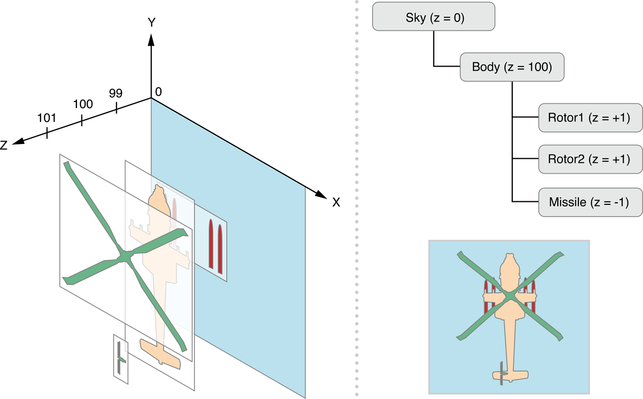
Figure 4-6 shows an example of a tree that uses z positions to determine the rendering order. In this example, the body of the helicopter is at a height of 100, and its children are rendered relative to its height. The two rotor nodes share the same height but do not overlap.
To summarize, you can use both tree order and z positions to determine your scene’s rendering order. When rendering a complex scene, you should disable the sorting behavior and use the z positions of nodes to create a deterministic scene order.
The Hit-Testing Order Is the Reverse of Drawing Order
In a scene, when SpriteKit processes touch or mouse events, it walks the scene to find the closest node that wants to accept the event. If that node doesn’t want the event, SpriteKit checks the next closest node, and so on. The order in which hit-testing is processed is essentially the reverse of drawing order.
For a node to be considered during hit-testing, its userInteractionEnabled property must be set to YES. The default value is NO for any node except a scene node. A node that wants to receive events needs to implement the appropriate responder methods from its parent class (UIResponder on iOS and NSResponder on OS X). This is one of the few places where you must implement platform-specific code in SpriteKit.
Sometimes, you also want to look for nodes directly, rather than relying on the standard event-handling mechanisms. In SpriteKit you can ask a node whether any of its descendants intersect a specific point in their coordinate system. Call the nodeAtPoint: method to find the first descendant that intersects the point, or use the nodesAtPoint: method to receive an array of all of the nodes that intersect the point.
Using a Node’s Depth to Add Other Effects
SpriteKit uses the zPosition value only to determine the hit testing and drawing order. You can also the z position to implement your own game effects. For example, you might use the height of a node to determine how it is rendered or how it moves onscreen. In this way, you can simulate fog or parallax effects. SpriteKit does not create these effects for you. Usually, you implement them by processing the scene immediately before it is rendered. See Advanced Scene Processing.
A Node Applies Many of Its Properties to Its Descendants
When you change a node’s property, often the effects are propagated to the node’s descendants. The net effect is that a child is rendered based not only on its own properties but also on the properties of its ancestors.
Property | Description |
|---|---|
The node’s coordinate system is scaled by these two factors. This property affects coordinate conversion, the node’s frame, drawing, and hit testing. Its descendants are similarly scaled. | |
The node’s coordinate system is rotated. This property affects coordinate conversion, the node’s frame, drawing, and hit testing. Its descendants are similarly scaled. | |
If the node is rendered using a blend mode, the alpha value is multiplied into any alpha value before the blend operation takes place. The descendants are similarly affected. | |
If a node is hidden, the node and its descendants are not rendered. | |
The speed at which a node processes actions is multiplied by this value. The descendants are similarly affected. |
Converting Between Coordinate Spaces
When working with the node tree, sometimes you need to convert a position from one coordinate space to another. For example, when specifying joints in the physics system, the joint positions are specified in scene coordinates. So, if you have those points in a local coordinate system, you need to convert them to the scene’s coordinate space.
Listing 4-2 shows how to convert a node’s position into the scene coordinate system. The scene is asked to perform the conversion. Remember that a node’s position is specified in its parent’s coordinate system, so the code passes node.parent as the node to convert from. You could perform the same conversion in reverse by calling the convertPoint:toNode: method.
Listing 4-2 Converting a node to the scene coordinate system
CGPoint positionInScene = [node.scene convertPoint:node.position fromNode:node.parent]; |
One situation where you need to perform coordinate conversions is when you perform event handling. Mouse and touch events need to be converted from window coordinates to view coordinates, and from there into the scene. To simplify the code you need to write, SpriteKit adds a few convenience methods:
In iOS, use the
locationInNode:andpreviousLocationInNode:onUITouchobjects to convert a touch location into a node’s coordinate system.In OS X, use the
locationInNode:method onNSEventobjects to convert a mouse event into a node’s coordinate system.
Copyright © 2015 Apple Inc. All Rights Reserved. Terms of Use | Privacy Policy | Updated: 2015-03-09