iOS Drawing Concepts
High-quality graphics are an important part of your app’s user interface. Providing high-quality graphics not only makes your app look good, but it also makes your app look like a natural extension to the rest of the system. iOS provides two primary paths for creating high-quality graphics in your system: OpenGL or native rendering using Quartz, Core Animation, and UIKit. This document describes native rendering. (To learn about OpenGL drawing, see OpenGL ES Programming Guide.)
Quartz is the main drawing interface, providing support for path-based drawing, anti-aliased rendering, gradient fill patterns, images, colors, coordinate-space transformations, and PDF document creation, display, and parsing. UIKit provides Objective-C wrappers for line art, Quartz images, and color manipulations. Core Animation provides the underlying support for animating changes in many UIKit view properties and can also be used to implement custom animations.
This chapter provides an overview of the drawing process for iOS apps, along with specific drawing techniques for each of the supported drawing technologies. You will also find tips and guidance on how to optimize your drawing code for the iOS platform.
The UIKit Graphics System
In iOS, all drawing to the screen—regardless of whether it involves OpenGL, Quartz, UIKit, or Core Animation—occurs within the confines of an instance of the UIView class or a subclass thereof. Views define the portion of the screen in which drawing occurs. If you use system-provided views, this drawing is handled for you automatically. If you define custom views, however, you must provide the drawing code yourself. If you use Quartz, Core Animation, and UIKit to draw, you use the drawing concepts described in the following sections.
In addition to drawing directly to the screen, UIKit also allows you to draw into offscreen bitmap and PDF graphics contexts. When you draw in an offscreen context, you are not drawing in a view, which means that concepts such as the view drawing cycle do not apply (unless you then obtain that image and draw it in an image view or similar).
The View Drawing Cycle
The basic drawing model for subclasses of the UIView class involves updating content on demand. The UIView class makes the update process easier and more efficient; however, by gathering the update requests you make and delivering them to your drawing code at the most appropriate time.
When a view is first shown or when a portion of the view needs to be redrawn, iOS asks the view to draw its content by calling the view’s drawRect: method.
There are several actions that can trigger a view update:
Moving or removing another view that was partially obscuring your view
Making a previously hidden view visible again by setting its
hiddenproperty toNOScrolling a view off of the screen and then back onto the screen
Explicitly calling the
setNeedsDisplayorsetNeedsDisplayInRect:method of your view
System views are redrawn automatically. For custom views, you must override the drawRect: method and perform all your drawing inside it. Inside your drawRect: method, use the native drawing technologies to draw shapes, text, images, gradients, or any other visual content you want. The first time your view becomes visible, iOS passes a rectangle to the view’s drawRect: method that contains your view’s entire visible area. During subsequent calls, the rectangle includes only the portion of the view that actually needs to be redrawn. For maximum performance, you should redraw only affected content.
After calling your drawRect: method, the view marks itself as updated and waits for new actions to arrive and trigger another update cycle. If your view displays static content, then all you need to do is respond to changes in your view’s visibility caused by scrolling and the presence of other views.
If you want to change the contents of the view, however, you must tell your view to redraw its contents. To do this, call the setNeedsDisplay or setNeedsDisplayInRect: method to trigger an update. For example, if you were updating content several times a second, you might want to set up a timer to update your view. You might also update your view in response to user interactions or the creation of new content in your view.
Coordinate Systems and Drawing in iOS
When an app draws something in iOS, it has to locate the drawn content in a two-dimensional space defined by a coordinate system. This notion might seem straightforward at first glance, but it isn’t. Apps in iOS sometimes have to deal with different coordinate systems when drawing.
In iOS, all drawing occurs in a graphics context. Conceptually, a graphics context is an object that describes where and how drawing should occur, including basic drawing attributes such as the colors to use when drawing, the clipping area, line width and style information, font information, compositing options, and so on.
In addition, as shown in Figure 1-1, each graphics context has a coordinate system. More precisely, each graphics context has three coordinate systems:
The drawing (user) coordinate system. This coordinate system is used when you issue drawing commands.
The view coordinate system (base space). This coordinate system is a fixed coordinate system relative to the view.
The (physical) device coordinate system. This coordinate system represents pixels on the physical screen.
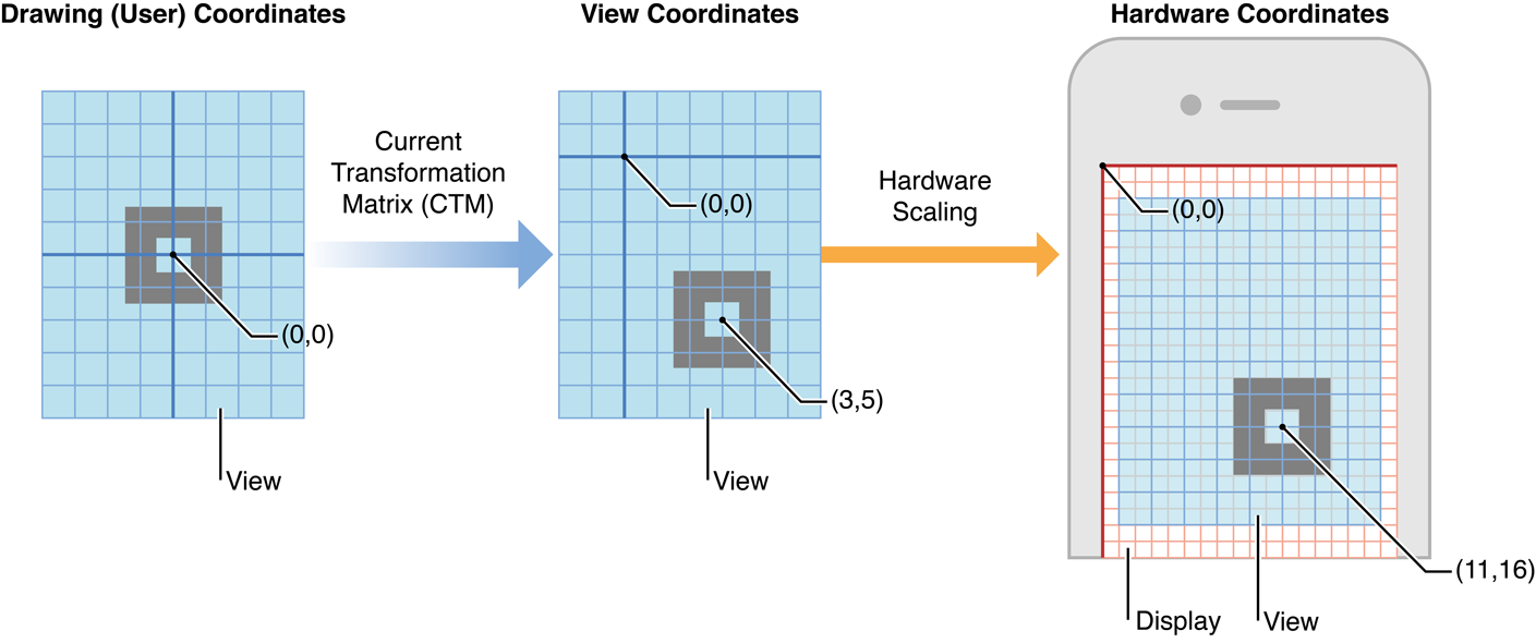
The drawing frameworks of iOS create graphics contexts for drawing to specific destinations—the screen, bitmaps, PDF content, and so on—and these graphics contexts establish the initial drawing coordinate system for that destination. This initial drawing coordinate system is known as the default coordinate system, and is a 1:1 mapping onto the view’s underlying coordinate system.
Each view also has a current transformation matrix (CTM), a mathematical matrix that maps the points in the current drawing coordinate system to the (fixed) view coordinate system. The app can modify this matrix (as described later) to change the behavior of future drawing operations.
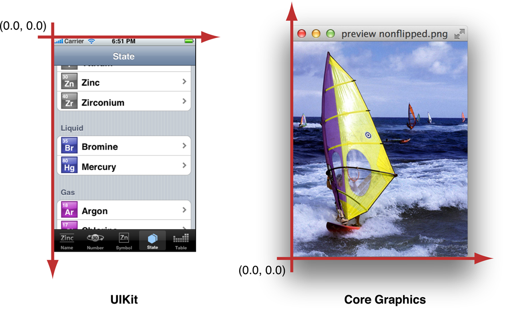
Each of the drawing frameworks of iOS establishes a default coordinate system based on the current graphics context. In iOS, there are two main types of coordinate systems:
An upper-left-origin coordinate system (ULO), in which the origin of drawing operations is at the upper-left corner of the drawing area, with positive values extending downward and to the right. The default coordinate system used by the UIKit and Core Animation frameworks is ULO-based.
A lower-left-origin coordinate system (LLO), in which the origin of drawing operations is at the lower-left corner of the drawing area, with positive values extending upward and to the right. The default coordinate system used by Core Graphics framework is LLO-based.
These coordinate systems are shown in Figure 1-2.
Before calling your view’s drawRect: method, UIKit establishes the default coordinate system for drawing to the screen by making a graphics context available for drawing operations. Within a view’s drawRect: method, an app can set graphics-state parameters (such as fill color) and draw to the current graphics context without needing to refer to the graphics context explicitly. This implicit graphics context establishes a ULO default coordinate system.
Points Versus Pixels
In iOS there is a distinction between the coordinates you specify in your drawing code and the pixels of the underlying device. When using native drawing technologies such as Quartz, UIKit, and Core Animation, the drawing coordinate space and the view’s coordinate space are both logical coordinate spaces, with distances measured in points. These logical coordinate systems are decoupled from the device coordinate space used by the system frameworks to manage the pixels onscreen.
The system automatically maps points in the view’s coordinate space to pixels in the device coordinate space, but this mapping is not always one-to-one. This behavior leads to an important fact that you should always remember:
One point does not necessarily correspond to one physical pixel.
The purpose of using points (and the logical coordinate system) is to provide a consistent size of output that is device independent. For most purposes, the actual size of a point is irrelevant. The goal of points is to provide a relatively consistent scale that you can use in your code to specify the size and position of views and rendered content. How points are actually mapped to pixels is a detail that is handled by the system frameworks. For example, on a device with a high-resolution screen, a line that is one point wide may actually result in a line that is two physical pixels wide. The result is that if you draw the same content on two similar devices, with only one of them having a high-resolution screen, the content appears to be about the same size on both devices.
In iOS, the UIScreen, UIView, UIImage, and CALayer classes provide properties to obtain (and, in some cases, set) a scale factor that describes the relationship between points and pixels for that particular object. For example, every UIKit view has a contentScaleFactor property. On a standard-resolution screen, the scale factor is typically 1.0. On a high-resolution screen, the scale factor is typically 2.0. In the future, other scale factors may also be possible. (In iOS prior to version 4, you should assume a scale factor of 1.0.)
Native drawing technologies, such as Core Graphics, take the current scale factor into account for you. For example, if one of your views implements a drawRect: method, UIKit automatically sets the scale factor for that view to the screen’s scale factor. In addition, UIKit automatically modifies the current transformation matrix of any graphics contexts used during drawing to take into account the view’s scale factor. Thus, any content you draw in your drawRect: method is scaled appropriately for the underlying device’s screen.
Because of this automatic mapping, when writing drawing code, pixels usually don’t matter. However, there are times when you might need to change your app’s drawing behavior depending on how points are mapped to pixels—to download higher-resolution images on devices with high-resolution screens or to avoid scaling artifacts when drawing on a low-resolution screen, for example.
In iOS, when you draw things onscreen, the graphics subsystem uses a technique called antialiasing to approximate a higher-resolution image on a lower-resolution screen. The best way to explain this technique is by example. When you draw a black vertical line on a solid white background, if that line falls exactly on a pixel, it appears as a series of black pixels in a field of white. If it appears exactly between two pixels, however, it appears as two grey pixels side-by-side, as shown in Figure 1-3.
Positions defined by whole-numbered points fall at the midpoint between pixels. For example, if you draw a one-pixel-wide vertical line from (1.0, 1.0) to (1.0, 10.0), you get a fuzzy grey line. If you draw a two-pixel-wide line, you get a solid black line because it fully covers two pixels (one on either side of the specified point). As a rule, lines that are an odd number of physical pixels wide appear softer than lines with widths measured in even numbers of physical pixels unless you adjust their position to make them cover pixels fully.
Where the scale factor comes into play is when determining how many pixels are covered by a one-point-wide line.
On a low-resolution display (with a scale factor of 1.0), a one-point-wide line is one pixel wide. To avoid antialiasing when you draw a one-point-wide horizontal or vertical line, if the line is an odd number of pixels in width, you must offset the position by 0.5 points to either side of a whole-numbered position. If the line is an even number of points in width, to avoid a fuzzy line, you must not do so.
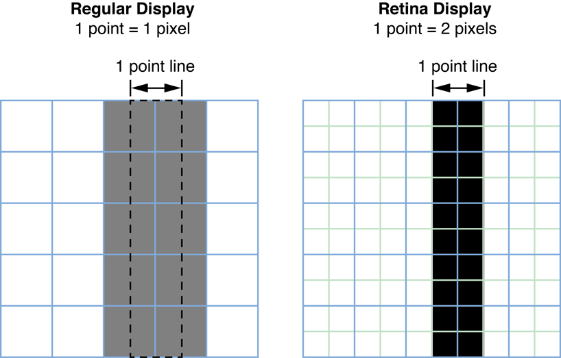
On a high-resolution display (with a scale factor of 2.0), a line that is one point wide is not antialiased at all because it occupies two full pixels (from -0.5 to +0.5). To draw a line that covers only a single physical pixel, you would need to make it 0.5 points in thickness and offset its position by 0.25 points. A comparison between the two types of screens is shown in Figure 1-4.
Of course, changing drawing characteristics based on scale factor may have unexpected consequences. A 1-pixel-wide line might look nice on some devices but on a high-resolution device might be so thin that it is difficult to see clearly. It is up to you to determine whether to make such a change.
Obtaining Graphics Contexts
Most of the time, graphics contexts are configured for you. Each view object automatically creates a graphics context so that your code can start drawing immediately as soon as your custom drawRect: method is called. As part of this configuration, the underlying UIView class creates a graphics context (a CGContextRef opaque type) for the current drawing environment.
If you want to draw somewhere other than your view (for example, to capture a series of drawing operations in a PDF or bitmap file), or if you need to call Core Graphics functions that require a context object, you must take additional steps to obtain a graphics context object. The sections below explain how.
For more information about graphics contexts, modifying the graphics state information, and using graphics contexts to create custom content, see Quartz 2D Programming Guide. For a list of functions used in conjunction with graphics contexts, see CGContext Reference, CGBitmapContext Reference, and CGPDFContext Reference.
Drawing to the Screen
If you use Core Graphics functions to draw to a view, either in the drawRect: method or elsewhere, you’ll need a graphics context for drawing. (The first parameter of many of these functions must be a CGContextRef object.) You can call the function UIGraphicsGetCurrentContext to get an explicit version of the same graphics context that’s made implicit in drawRect:. Because it’s the same graphics context, the drawing functions should also make reference to a ULO default coordinate system.
If you want to use Core Graphics functions to draw in a UIKit view, you should use the ULO coordinate system of UIKit for drawing operations. Alternatively, you can apply a flip transform to the CTM and then draw an object in the UIKit view using Core Graphics native LLO coordinate system. Flipping the Default Coordinate System discusses flip transforms in detail.
The UIGraphicsGetCurrentContext function always returns the graphics context currently in effect. For example, if you create a PDF context and then call UIGraphicsGetCurrentContext, you’d receive that PDF context. You must use the graphics context returned by UIGraphicsGetCurrentContext if you use Core Graphics functions to draw to a view.
Drawing to Bitmap Contexts and PDF Contexts
UIKit provides functions for rendering images in a bitmap graphics context and for generating PDF content by drawing in a PDF graphics context. Both of these approaches require that you first call a function that creates a graphics context—a bitmap context or a PDF context, respectively. The returned object serves as the current (and implicit) graphics context for subsequent drawing and state-setting calls. When you finish drawing in the context, you call another function to close the context.
Both the bitmap context and the PDF context provided by UIKit establish a ULO default coordinate system. Core Graphics has corresponding functions for rendering in a bitmap graphics context and for drawing in a PDF graphics context. The context that an app directly creates through Core Graphics, however, establishes a LLO default coordinate system.
For details, see Drawing and Creating Images (for drawing to bitmap contexts) and Generating PDF Content (for drawing to PDF contexts).
Color and Color Spaces
iOS supports the full range of color spaces available in Quartz; however, most apps should need only the RGB color space. Because iOS is designed to run on embedded hardware and display graphics onscreen, the RGB color space is the most appropriate one to use.
The UIColor object provides convenience methods for specifying color values using RGB, HSB, and grayscale values. When creating colors in this way, you never need to specify the color space. It is determined for you automatically by the UIColor object.
You can also use the CGContextSetRGBStrokeColor and CGContextSetRGBFillColor functions in the Core Graphics framework to create and set colors. Although the Core Graphics framework includes support for creating colors using other color spaces, and for creating custom color spaces, using those colors in your drawing code is not recommended. Your drawing code should always use RGB colors.
Drawing with Quartz and UIKit
Quartz is the general name for the native drawing technology in iOS. The Core Graphics framework is at the heart of Quartz, and is the primary interface you use for drawing content. This framework provides data types and functions for manipulating the following:
Graphics contexts
Paths
Images and bitmaps
Transparency layers
Colors, pattern colors, and color spaces
Gradients and shadings
Fonts
PDF content
UIKit builds on the basic features of Quartz by providing a focused set of classes for graphics-related operations. The UIKit graphics classes are not intended as a comprehensive set of drawing tools—Core Graphics already provides that. Instead, they provide drawing support for other UIKit classes. UIKit support includes the following classes and functions:
UIImage, which implements an immutable class for displaying imagesUIColor, which provides basic support for device colorsUIFont, which provides font information for classes that need itUIScreen, which provides basic information about the screenUIBezierPath, which enables your app to draw lines, arcs, ovals, and other shapes.Functions for generating a JPEG or PNG representation of a
UIImageobjectFunctions for drawing to a bitmap graphics context
Functions for generating PDF data by drawing to a PDF graphics context
Functions for drawing rectangles and clipping the drawing area
Functions for changing and getting the current graphics context
For information about the classes and methods that comprise UIKit, see UIKit Framework Reference. For more information about the opaque types and functions that comprise the Core Graphics framework, see Core Graphics Framework Reference.
Configuring the Graphics Context
Before calling your drawRect: method, the view object creates a graphics context and sets it as the current context. This context exists only for the lifetime of the drawRect: call. You can retrieve a pointer to this graphics context by calling the UIGraphicsGetCurrentContext function. This function returns a reference to a CGContextRef type, which you pass to Core Graphics functions to modify the current graphics state. Table 1-1 lists the main functions you use to set different aspects of the graphics state. For a complete list of functions, see CGContext Reference. This table also lists UIKit alternatives where they exist.
Graphics state | Core Graphics functions | UIKit alternatives |
|---|---|---|
Current transformation matrix (CTM) | None | |
Clipping area |
| |
Line: Width, join, cap, dash, miter limit | None | |
Accuracy of curve estimation | None | |
Anti-aliasing setting | None | |
Color: Fill and stroke settings |
| |
Alpha global value (transparency) | None | |
Rendering intent | None | |
Color space: Fill and stroke settings |
| |
Text: Font, font size, character spacing, text drawing mode |
| |
Blend mode | The |
The graphics context contains a stack of saved graphics states. When Quartz creates a graphics context, the stack is empty. Using the CGContextSaveGState function pushes a copy of the current graphics state onto the stack. Thereafter, modifications you make to the graphics state affect subsequent drawing operations but do not affect the copy stored on the stack. When you are done making modifications, you can return to the previous graphics state by popping the saved state off the top of the stack using the CGContextRestoreGState function. Pushing and popping graphics states in this manner is a fast way to return to a previous state and eliminates the need to undo each state change individually. It is also the only way to restore some aspects of the state, such as the clipping path, back to their original settings.
For general information about graphics contexts and using them to configure the drawing environment, see Graphics Contexts in Quartz 2D Programming Guide.
Creating and Drawing Paths
A path is a vector-based shapes created from a sequence of lines and Bézier curves. UIKit includes the UIRectFrame and UIRectFill functions (among others) for drawing simple paths such as rectangles in your views. Core Graphics also includes convenience functions for creating simple paths such as rectangles and ellipses.
For more complex paths, you must create the path yourself using the UIBezierPath class of UIKit, or using the functions that operate on the CGPathRef opaque type in the Core Graphics framework. Although you can construct a path without a graphics context using either API, the points in the path still must refer to the current coordinate system (which either has a ULO or LLO orientation), and you still need a graphics context to actually render the path.
When drawing a path, you must have a current context set. This context can be a custom view’s context (in drawRect:), a bitmap context, or a PDF context. The coordinate system determines how the path is rendered. UIBezierPath assumes a ULO coordinate system. Thus, if your view is flipped (to use LLO coordinates), the resulting shape may render differently than intended. For best results, you should always specify points relative to the origin of the current coordinate system of the graphics context used for rendering.
For creating paths in iOS, it is recommended that you use UIBezierPath instead of CGPath functions unless you need some of the capabilities that only Core Graphics provides, such as adding ellipses to paths. For more on creating and rendering paths in UIKit, see Drawing Shapes Using Bézier Paths.
For information on using UIBezierPath to draw paths, see Drawing Shapes Using Bézier Paths. For information on how to draw paths using Core Graphics, including information about how you specify the points for complex path elements, see Paths in Quartz 2D Programming Guide. For information on the functions you use to create paths, see CGContext Reference and CGPath Reference.
Creating Patterns, Gradients, and Shadings
The Core Graphics framework includes additional functions for creating patterns, gradients, and shadings. You use these types to create non monochrome colors and use them to fill the paths you create. Patterns are created from repeating images or content. Gradients and shadings provide different ways to create smooth transitions from color to color.
The details for creating and using patterns, gradients, and shadings are all covered in Quartz 2D Programming Guide.
Customizing the Coordinate Space
By default, UIKit creates a straightforward current transformation matrix that maps points onto pixels. Although you can do all of your drawing without modifying that matrix, sometimes it can be convenient to do so.
When your view’s drawRect: method is first called, the CTM is configured so that the origin of the coordinate system matches the your view’s origin, its positive X axis extends to the right, and its positive Y axis extends down. However, you can change the CTM by adding scaling, rotation, and translation factors to it and thereby change the size, orientation, and position of the default coordinate system relative to the underlying view or window.
Using Coordinate Transforms to Improve Drawing Performance
Modifying the CTM is a standard technique for drawing content in a view because it allows you to reuse paths, which potentially reduces the amount of computation required while drawing. For example, if you want to draw a square starting at the point (20, 20), you could create a path that moves to (20, 20) and then draws the needed set of lines to complete the square. However, if you later decide to move that square to the point (10, 10), you would have to recreate the path with the new starting point. Because creating paths is a relatively expensive operation, it is preferable to create a square whose origin is at (0, 0) and to modify the CTM so that the square is drawn at the desired origin.
In the Core Graphics framework, there are two ways to modify the CTM. You can modify the CTM directly using the CTM manipulation functions defined in CGContext Reference. You can also create a CGAffineTransform structure, apply any transformations you want, and then concatenate that transform onto the CTM. Using an affine transform lets you group transformations and then apply them to the CTM all at once. You can also evaluate and invert affine transforms and use them to modify point, size, and rectangle values in your code. For more information on using affine transforms, see Quartz 2D Programming Guide and CGAffineTransform Reference.
Flipping the Default Coordinate System
Flipping in UIKit drawing modifies the backing CALayer to align a drawing environment having a LLO coordinate system with the default coordinate system of UIKit. If you only use UIKit methods and function for drawing, you shouldn’t need to flip the CTM. However, if you mix Core Graphics or Image I/O function calls with UIKit calls, flipping the CTM might be necessary.
Specifically, if you draw an image or PDF document by calling Core Graphics functions directly, the object is rendered upside-down in the view’s context. You must flip the CTM to display the image and pages correctly.
To flip a object drawn to a Core Graphics context so that it appears correctly when displayed in a UIKit view, you must modify the CTM in two steps. You translate the origin to the upper-left corner of the drawing area, and then you apply a scale translation, modifying the y-coordinate by -1. The code for doing this looks similar to the following:
CGContextSaveGState(graphicsContext); |
CGContextTranslateCTM(graphicsContext, 0.0, imageHeight); |
CGContextScaleCTM(graphicsContext, 1.0, -1.0); |
CGContextDrawImage(graphicsContext, image, CGRectMake(0, 0, imageWidth, imageHeight)); |
CGContextRestoreGState(graphicsContext); |
If you create a UIImage object initialized with a Core Graphics image object, UIKit performs the flip transform for you. Every UIImage object is backed by a CGImageRef opaque type. You can access the Core Graphics object through the CGImage property and do some work with the image. (Core Graphics has image-related facilities not available in UIKit.) When you are finished, you can recreate the UIImage object from the modified CGImageRef object.
Side Effects of Drawing with Different Coordinate Systems
Some rendering oddities are brought to light when you draw an object with with reference to the default coordinate system of one drawing technology and then render it in a graphics context of the other. You may want to adjust your code to account for these side effects.
Arcs and Rotations
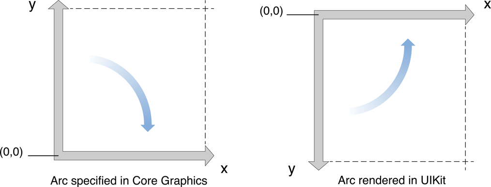
If you draw a path with functions such as CGContextAddArc and CGPathAddArc and assume a LLO coordinate system, then you need to flip the CTM to render the arc correctly in a UIKit view. However, if you use the same function to create an arc with points located in a ULO coordinate system and then render the path in a UIKit view, you’ll notice that the arc is an altered version of its original. The terminating endpoint of the arc now points in the opposite direction of what that endpoint would do were the arc created using the UIBezierPath class. For example, a downward-pointing arrow now points upward (as shown in Figure 1-5), and the direction in which the arc “bends” is also different. You must change the direction of Core Graphics-drawn arcs to account for the ULO-based coordinate system; this direction is controlled by the startAngle and endAngle parameters of those functions.
You can observe the same kind of mirroring effect if you rotate an object (for example, by calling CGContextRotateCTM). If you rotate an object using Core Graphics calls that make reference to a ULO coordinate system, the direction of the object when rendered in UIKit is reversed. You must account for the different directions of rotation in your code; with CGContextRotateCTM, you do this by inverting the sign of the angle parameter (so, for example, a negative value becomes a positive value).
Shadows
The direction a shadow falls from its object is specified by an offset value, and the meaning of that offset is a convention of a drawing framework. In UIKit, positive x and y offsets make a shadow go down and to the right of an object. In Core Graphics, positive x and y offsets make a shadow go up and to the right of an object. Flipping the CTM to align an object with the default coordinate system of UIKit does not affect the object’s shadow, and so a shadow does not correctly track its object. To get it to track correctly, you must modify the offset values appropriately for the current coordinate system.
Applying Core Animation Effects
Core Animation is an Objective-C framework that provides infrastructure for creating fluid, real-time animations quickly and easily. Core Animation is not a drawing technology itself, in the sense that it does not provide primitive routines for creating shapes, images, or other types of content. Instead, it is a technology for manipulating and displaying content that you created using other technologies.
Most apps can benefit from using Core Animation in some form in iOS. Animations provide feedback to the user about what is happening. For example, when the user navigates through the Settings app, screens slide in and out of view based on whether the user is navigating further down the preferences hierarchy or back up to the root node. This kind of feedback is important and provides contextual information for the user. It also enhances the visual style of an app.
In most cases, you may be able to reap the benefits of Core Animation with very little effort. For example, several properties of the UIView class (including the view’s frame, center, color, and opacity—among others) can be configured to trigger animations when their values change. You have to do some work to let UIKit know that you want these animations performed, but the animations themselves are created and run automatically for you. For information about how to trigger the built-in view animations, see Animating Views in UIView Class Reference.
When you go beyond the basic animations, you must interact more directly with Core Animation classes and methods. The following sections provide information about Core Animation and show you how to work with its classes and methods to create typical animations in iOS. For additional information about Core Animation and how to use it, see Core Animation Programming Guide.
About Layers
The key technology in Core Animation is the layer object. Layers are lightweight objects that are similar in nature to views, but that are actually model objects that encapsulate geometry, timing, and visual properties for the content you want to display. The content itself is provided in one of three ways:
You can assign a
CGImageRefto thecontentsproperty of the layer object.You can assign a delegate to the layer and let the delegate handle the drawing.
You can subclass
CALayerand override one of the display methods.
When you manipulate a layer object’s properties, what you are actually manipulating is the model-level data that determines how the associated content should be displayed. The actual rendering of that content is handled separately from your code and is heavily optimized to ensure it is fast. All you must do is set the layer content, configure the animation properties, and then let Core Animation take over.
For more information about layers and how they are used, see Core Animation Programming Guide.
About Animations
When it comes to animating layers, Core Animation uses separate animation objects to control the timing and behavior of the animation. The CAAnimation class and its subclasses provide different types of animation behaviors that you can use in your code. You can create simple animations that migrate a property from one value to another, or you can create complex keyframe animations that track the animation through the set of values and timing functions you provide.
Core Animation also lets you group multiple animations together into a single unit, called a transaction. The CATransaction object manages the group of animations as a unit. You can also use the methods of this class to set the duration of the animation.
For examples of how to create custom animations, see Animation Types and Timing Programming Guide.
Accounting for Scale Factors in Core Animation Layers
Apps that use Core Animation layers directly to provide content may need to adjust their drawing code to account for scale factors. Normally, when you draw in your view’s drawRect: method, or in the drawLayer:inContext: method of the layer’s delegate, the system automatically adjusts the graphics context to account for scale factors. However, knowing or changing that scale factor might still be necessary when your view does one of the following:
Creates additional Core Animation layers with different scale factors and composites them into its own content
Sets the
contentsproperty of a Core Animation layer directly
Core Animation’s compositing engine looks at the contentsScale property of each layer to determine whether the contents of that layer need to be scaled during compositing. If your app creates layers without an associated view, each new layer object’s scale factor is initially set to 1.0. If you do not change that scale factor, and if you subsequently draw the layer on a high-resolution screen, the layer’s contents are scaled automatically to compensate for the difference in scale factors. If you do not want the contents to be scaled, you can change the layer’s scale factor to 2.0 by setting a new value for the contentsScale property, but if you do so without providing high-resolution content, your existing content may appear smaller than you were expecting. To fix that problem, you need to provide higher-resolution content for your layer.
Adjusting the content of your layer to accommodate different scale factors is most appropriate when you set the contents property of a layer directly. Quartz images have no notion of scale factors and therefore work directly with pixels. Therefore, before creating the CGImageRef object you plan to use for the layer’s contents, check the scale factor and adjust the size of your image accordingly. Specifically, load an appropriately sized image from your app bundle or use the UIGraphicsBeginImageContextWithOptions function to create an image whose scale factor matches the scale factor of your layer. If you do not create a high-resolution bitmap, the existing bitmap may be scaled as discussed previously.
For information on how to specify and load high-resolution images, see Loading Images into Your App. For information about how to create high-resolution images, see Drawing to Bitmap Contexts and PDF Contexts.
Copyright © 2012 Apple Inc. All Rights Reserved. Terms of Use | Privacy Policy | Updated: 2012-09-19