Graphics Rendering: Render Command Encoder
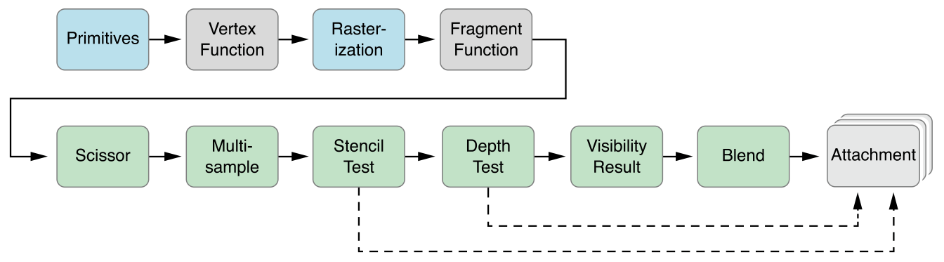
This chapter describes how to create and work with MTLRenderCommandEncoder and MTLParallelRenderCommandEncoder objects, which are used to encode graphics rendering commands into a command buffer. MTLRenderCommandEncoder commands describe a graphics rendering pipeline, as seen in Figure 5-1.
A MTLRenderCommandEncoder object represents a single rendering command encoder. A MTLParallelRenderCommandEncoder object enables a single rendering pass to be broken into a number of separate MTLRenderCommandEncoder objects, each of which may be assigned to a different thread. The commands from the different render command encoders are then chained together and executed in a consistent, predictable order, as described in Multiple Threads for a Rendering Pass.
Creating and Using a Render Command Encoder
To create, initialize, and use a single render command encoder:
Create a
MTLRenderPassDescriptorobject to define a collection of attachments that serve as the rendering destination for the graphics commands in the command buffer for that rendering pass. Typically, you create aMTLRenderPassDescriptorobject once and reuse it each time your app renders a frame. See Creating a Render Pass Descriptor.Create a
MTLRenderCommandEncoderobject by calling therenderCommandEncoderWithDescriptor:method ofMTLCommandBufferwith the specified render pass descriptor. See Using the Render Pass Descriptor to Create a Render Command Encoder.Create a
MTLRenderPipelineStateobject to define the state of the graphics rendering pipeline (including shaders, blending, multisampling, and visibility testing) for one or more draw calls. To use this render pipeline state for drawing primitives, call thesetRenderPipelineState:method ofMTLRenderCommandEncoder. For details, see Creating a Render Pipeline State.Set textures, buffers, and samplers to be used by the render command encoder, as described in Specifying Resources for a Render Command Encoder.
Call
MTLRenderCommandEncodermethods to specify additional fixed-function state, including the depth and stencil state, as explained in Fixed-Function State Operations.Finally, call
MTLRenderCommandEncodermethods to draw graphics primitives, as described in Drawing Geometric Primitives.
Creating a Render Pass Descriptor
A MTLRenderPassDescriptor object represents the destination for the encoded rendering commands, which is a collection of attachments. The properties of a render pass descriptor may include an array of up to four attachments for color pixel data, one attachment for depth pixel data, and one attachment for stencil pixel data. The renderPassDescriptor convenience method creates a MTLRenderPassDescriptor object with color, depth, and stencil attachment properties with default attachment state. The visibilityResultBuffer property specifies a buffer where the device can update to indicate whether any samples pass the depth and stencil tests—for details, see Fixed-Function State Operations.
Each individual attachment, including the texture that will be written to, is represented by an attachment descriptor. For an attachment descriptor, the pixel format of the associated texture must be chosen appropriately to store color, depth, or stencil data. For a color attachment descriptor, MTLRenderPassColorAttachmentDescriptor, use a color-renderable pixel format. For a depth attachment descriptor, MTLRenderPassDepthAttachmentDescriptor, use a depth-renderable pixel format, such as MTLPixelFormatDepth32Float. For a stencil attachment descriptor, MTLRenderPassStencilAttachmentDescriptor, use a stencil-renderable pixel format, such as MTLPixelFormatStencil8.
The amount of memory the texture actually uses per pixel on the device does not always match the size of the texture’s pixel format in the Metal framework code, because the device adds padding for alignment or other purposes. See the Metal Feature Set Tables chapter for how much memory is actually used for each pixel format, as well limitations on the size and number of attachments.
Load and Store Actions
The loadAction and storeAction properties of an attachment descriptor specify an action that is performed at either the start or end of a rendering pass. (For MTLParallelRenderCommandEncoder, the load and store actions occur at the boundaries of the overall command, not for each of its MTLRenderCommandEncoder objects. For details, see Multiple Threads for a Rendering Pass.)
Possible loadAction values include:
MTLLoadActionClear, which writes the same value to every pixel in the specified attachment descriptor. For more detail about this action, see Specifying the Clear Load Action.MTLLoadActionLoad, which preserves the existing contents of the texture.MTLLoadActionDontCare, which allows each pixel in the attachment to take on any value at the start of the rendering pass.
If your application will render all pixels of the attachment for a given frame, use the default load action MTLLoadActionDontCare. The MTLLoadActionDontCare action allows the GPU to avoid loading the existing contents of the texture, ensuring the best performance. Otherwise, you can use the MTLLoadActionClear action to clear the previous contents of the attachment, or the MTLLoadActionLoad action to preserve them. The MTLLoadActionClear action also avoids loading the existing texture contents, but it incurs the cost of filling the destination with a solid color.
Possible storeAction values include:
MTLStoreActionStore, which saves the final results of the rendering pass into the attachment.MTLStoreActionMultisampleResolve, which resolves the multisample data from the render target into single sample values, stores them in the texture specified by the attachment propertyresolveTexture, and leaves the contents of the attachment undefined. For details, see Example: Creating a Render Pass Descriptor for Multisampled Rendering.MTLStoreActionDontCare, which leaves the attachment in an undefined state after the rendering pass is complete. This may improve performance as it enables the implementation to avoid any work necessary to preserve the rendering results.
For color attachments, the MTLStoreActionStore action is the default store action, because applications almost always preserve the final color values in the attachment at the end of rendering pass. For depth and stencil attachments, MTLStoreActionDontCare is the default store action, because those attachments typically do not need to be preserved after the rendering pass is complete.
Specifying the Clear Load Action
If the loadAction property of an attachment descriptor is set to MTLLoadActionClear, then a clearing value is written to every pixel in the specified attachment descriptor at the start of a rendering pass. The clearing value property depends upon the type of attachment.
For
MTLRenderPassColorAttachmentDescriptor,clearColorcontains aMTLClearColorvalue that consists of four double-precision floating-point RGBA components and is used to clear the color attachment. TheMTLClearColorMakefunction creates a clear color value from red, green, blue, and alpha components. The default clear color is (0.0, 0.0, 0.0, 1.0), or opaque black.For
MTLRenderPassDepthAttachmentDescriptor,clearDepthcontains one double-precision floating-point clearing value in the range [0.0, 1.0] that is used to clear the depth attachment. The default value is 1.0.For
MTLRenderPassStencilAttachmentDescriptor,clearStencilcontains one 32-bit unsigned integer that is used to clear the stencil attachment. The default value is 0.
Example: Creating a Render Pass Descriptor with Load and Store Actions
Listing 5-1 creates a simple render pass descriptor with color and depth attachments. First, two texture objects are created, one with a color-renderable pixel format and the other with a depth pixel format. Next the renderPassDescriptor convenience method of MTLRenderPassDescriptor creates a default render pass descriptor. Then the color and depth attachments are accessed through the properties of MTLRenderPassDescriptor. The textures and actions are set in colorAttachments[0], which represents the first color attachment (at index 0 in the array), and the depth attachment.
Listing 5-1 Creating a Render Pass Descriptor with Color and Depth Attachments
MTLTextureDescriptor *colorTexDesc = [MTLTextureDescriptor |
texture2DDescriptorWithPixelFormat:MTLPixelFormatRGBA8Unorm |
width:IMAGE_WIDTH height:IMAGE_HEIGHT mipmapped:NO]; |
id <MTLTexture> colorTex = [device newTextureWithDescriptor:colorTexDesc]; |
MTLTextureDescriptor *depthTexDesc = [MTLTextureDescriptor |
texture2DDescriptorWithPixelFormat:MTLPixelFormatDepth32Float |
width:IMAGE_WIDTH height:IMAGE_HEIGHT mipmapped:NO]; |
id <MTLTexture> depthTex = [device newTextureWithDescriptor:depthTexDesc]; |
MTLRenderPassDescriptor *renderPassDesc = [MTLRenderPassDescriptor renderPassDescriptor]; |
renderPassDesc.colorAttachments[0].texture = colorTex; |
renderPassDesc.colorAttachments[0].loadAction = MTLLoadActionClear; |
renderPassDesc.colorAttachments[0].storeAction = MTLStoreActionStore; |
renderPassDesc.colorAttachments[0].clearColor = MTLClearColorMake(0.0,1.0,0.0,1.0); |
renderPassDesc.depthAttachment.texture = depthTex; |
renderPassDesc.depthAttachment.loadAction = MTLLoadActionClear; |
renderPassDesc.depthAttachment.storeAction = MTLStoreActionStore; |
renderPassDesc.depthAttachment.clearDepth = 1.0; |
Example: Creating a Render Pass Descriptor for Multisampled Rendering
To use the MTLStoreActionMultisampleResolve action, you must set the texture property to a multisample-type texture, and the resolveTexture property will contain the result of the multisample resolve operation. (If texture does not support multisampling, then the result of a multisample resolve action is undefined.) The resolveLevel, resolveSlice, and resolveDepthPlane properties may also be used for the multisample resolve operation to specify the mipmap level, cube slice, and depth plane of the multisample texture, respectively. In most cases, the default values for resolveLevel, resolveSlice, and resolveDepthPlane are usable. In Listing 5-2, an attachment is initially created and then its loadAction, storeAction, texture, and resolveTexture properties are set to support multisample resolve.
Listing 5-2 Setting Properties for an Attachment with Multisample Resolve
MTLTextureDescriptor *colorTexDesc = [MTLTextureDescriptor |
texture2DDescriptorWithPixelFormat:MTLPixelFormatRGBA8Unorm |
width:IMAGE_WIDTH height:IMAGE_HEIGHT mipmapped:NO]; |
id <MTLTexture> colorTex = [device newTextureWithDescriptor:colorTexDesc]; |
MTLTextureDescriptor *msaaTexDesc = [MTLTextureDescriptor |
texture2DDescriptorWithPixelFormat:MTLPixelFormatRGBA8Unorm |
width:IMAGE_WIDTH height:IMAGE_HEIGHT mipmapped:NO]; |
msaaTexDesc.textureType = MTLTextureType2DMultisample; |
msaaTexDesc.sampleCount = sampleCount; // must be > 1 |
id <MTLTexture> msaaTex = [device newTextureWithDescriptor:msaaTexDesc]; |
MTLRenderPassDescriptor *renderPassDesc = [MTLRenderPassDescriptor renderPassDescriptor]; |
renderPassDesc.colorAttachments[0].texture = msaaTex; |
renderPassDesc.colorAttachments[0].resolveTexture = colorTex; |
renderPassDesc.colorAttachments[0].loadAction = MTLLoadActionClear; |
renderPassDesc.colorAttachments[0].storeAction = MTLStoreActionMultisampleResolve; |
renderPassDesc.colorAttachments[0].clearColor = MTLClearColorMake(0.0,1.0,0.0,1.0); |
Using the Render Pass Descriptor to Create a Render Command Encoder
After you create a render pass descriptor and specify its properties, use the renderCommandEncoderWithDescriptor: method of a MTLCommandBuffer object to create a render command encoder, as shown in Listing 5-3.
Listing 5-3 Creating a Render Command Encoder with the Render Pass Descriptor
id <MTLRenderCommandEncoder> renderCE = [commandBuffer |
renderCommandEncoderWithDescriptor:renderPassDesc]; |
Displaying Rendered Content with Core Animation
Core Animation defines the CAMetalLayer class, which is designed for the specialized behavior of a layer-backed view whose content is rendered using Metal. A CAMetalLayer object represents information about the geometry of the content (position and size), its visual attributes (background color, border, and shadow), and the resources used by Metal to present the content in a color attachment. It also encapsulates the timing of content presentation so that the content can be displayed as soon as it is available or at a specified time. For more information about Core Animation, see the Core Animation Programming Guide.
Core Animation also defines the CAMetalDrawable protocol for objects that are displayable resources. The CAMetalDrawable protocol extends MTLDrawable and provides an object that conforms to the MTLTexture protocol, so it can be used as a destination for rendering commands. To render into a CAMetalLayer object, you should get a new CAMetalDrawable object for each rendering pass, get the MTLTexture object that it provides, and use that texture to create the color attachment. Unlike color attachments, creation and destruction of a depth or stencil attachment are costly. If you need either depth or stencil attachments, create them once and then reuse them each time a frame is rendered.
Typically, you use the layerClass method to designate CAMetalLayer as the backing layer type for your own custom UIView subclass, as shown in Listing 5-4. Otherwise, you can create a CAMetalLayer with its init method and include the layer in an existing view.
Listing 5-4 Using CAMetalLayer as the backing layer for a UIView subclass
+ (id) layerClass { |
return [CAMetalLayer class]; |
} |
To display content rendered by Metal in the layer, you must obtain a displayable resource (a CAMetalDrawable object) from the CAMetalLayer object and then render to the texture in this resource by attaching it to a MTLRenderPassDescriptor object. To do this, you first set properties of the CAMetalLayer object that describe the drawable resources it provides, then call its nextDrawable method each time you begin rendering a new frame. If the CAMetalLayer properties are not set, the nextDrawable method call fails. The following CAMetalLayer properties describe the drawable object:
The
deviceproperty declares theMTLDeviceobject that the resource is created from.The
pixelFormatproperty declares the pixel format of the texture. The supported values areMTLPixelFormatBGRA8Unorm(the default) andMTLPixelFormatBGRA8Unorm_sRGB.The
drawableSizeproperty declares the dimensions of the texture in device pixels. To ensure that your app renders content at the precise dimensions of the display (without requiring an additional sampling stage on some devices), take the target screen’snativeScaleornativeBoundsproperty into account when calculating the desired size for your layer.The
framebufferOnlyproperty declares whether the texture can be used only as an attachment (YES) or whether it can also be used for texture sampling and pixel read/write operations (NO). IfYES, the layer object can optimize the texture for display. For most apps, the recommended value isYES.The
presentsWithTransactionproperty declares whether changes to the layer's rendered resource are updated with standard Core Animation transaction mechanisms (YES) or are updated asynchronously to normal layer updates (NO, the default value).
If the nextDrawable method succeeds, it returns a CAMetalDrawable object with the following read-only properties:
The
textureproperty holds the texture object. You use this as an attachment when creating your rendering pipeline (MTLRenderPipelineColorAttachmentDescriptorobject).The
layerproperty points to theCAMetalLayerobject that responsible for displaying the drawable.
To display the contents of a drawable object after rendering is complete, you must submit it to Core Animation by calling the drawable object’s present method. To synchronize presentation of a drawable with completion of the command buffer responsible for its rendering, you can call either the presentDrawable: or presentDrawable:atTime: convenience method on a MTLCommandBuffer object. These methods use the scheduled handler (see Registering Handler Blocks for Command Buffer Execution) to call the drawable’s present method, which covers most scenarios. The presentDrawable:atTime: method provides further control over when the drawable is presented.
Creating a Render Pipeline State
To use a MTLRenderCommandEncoder object to encode rendering commands, you must first specify a MTLRenderPipelineState object to define the graphics state for any draw calls. A render pipeline state object is a long-lived persistent object that can be created outside of a render command encoder, cached in advance, and reused across several render command encoders. When describing the same set of graphics state, reusing a previously created render pipeline state object may avoid expensive operations that re-evaluate and translate the specified state to GPU commands.
A render pipeline state is an immutable object. To create a render pipeline state, you first create and configure a mutable MTLRenderPipelineDescriptor object that describes the attributes of a render pipeline state. Then, you use the descriptor to create a MTLRenderPipelineState object.
Creating and Configuring a Render Pipeline Descriptor
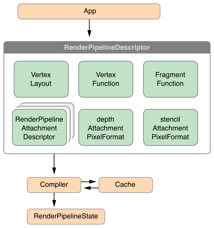
To create a render pipeline state, first create a MTLRenderPipelineDescriptor object, which has properties that describe the graphics rendering pipeline state you want to use during the rendering pass, as depicted in Figure 5-2. The colorAttachments property of the new MTLRenderPipelineDescriptor object contains an array of MTLRenderPipelineColorAttachmentDescriptor objects, and each descriptor represents a color attachment state that specifies the blend operations and factors for that attachment, as detailed in Configuring Blending in a Render Pipeline Attachment Descriptor. The attachment descriptor also specifies the pixel format of the attachment, which must match the pixel format for the texture of the render pipeline descriptor with the corresponding attachment index, or an error occurs.
In addition to configuring the color attachments, set these properties for the MTLRenderPipelineDescriptor object:
Set the
depthAttachmentPixelFormatproperty to match the pixel format for the texture ofdepthAttachmentinMTLRenderPassDescriptor.Set the
stencilAttachmentPixelFormatproperty to match the pixel format for the texture ofstencilAttachmentinMTLRenderPassDescriptor.To specify the vertex or fragment shader in the render pipeline state, set the
vertexFunctionorfragmentFunctionproperty, respectively. SettingfragmentFunctiontonildisables the rasterization of pixels into the specified color attachment, which is typically used for depth-only rendering or for outputting data into a buffer object from the vertex shader.If the vertex shader has an argument with per-vertex input attributes, set the
vertexDescriptorproperty to describe the organization of the vertex data in that argument, as described in Vertex Descriptor for Data Organization.The default value of
YESfor therasterizationEnabledproperty is sufficient for most typical rendering tasks. To use only the vertex stage of the graphics pipeline (for example, to gather data transformed in a vertex shader), set this property toNO.If the attachment supports multisampling (that is, the attachment is a
MTLTextureType2DMultisampletype texture), then multiple samples can be created per pixel. To determine how fragments combine to provide pixel coverage, use the followingMTLRenderPipelineDescriptorproperties.The
sampleCountproperty determines the number of samples for each pixel. WhenMTLRenderCommandEncoderis created, thesampleCountfor the textures for all attachments must match thissampleCountproperty. If the attachment cannot support multisampling, thensampleCountis 1, which is also the default value.If
alphaToCoverageEnabledis set toYES, then the alpha channel fragment output forcolorAttachments[0]is read and used to determine a coverage mask.If
alphaToOneEnabledis set toYES, then alpha channel fragment values forcolorAttachments[0]are forced to 1.0, which is the largest representable value. (Other attachments are unaffected.)
Creating a Render Pipeline State from a Descriptor
After creating a render pipeline descriptor and specifying its properties, use it to create the MTLRenderPipelineState object. Because creating a render pipeline state can require an expensive evaluation of graphics state and a possible compilation of the specified graphics shaders, you can use either a blocking or an asynchronous method to schedule such work in a way that best fits the design of your app.
To synchronously create the render pipeline state object, call either the
newRenderPipelineStateWithDescriptor:error:ornewRenderPipelineStateWithDescriptor:options:reflection:error:method of aMTLDeviceobject. These methods block the current thread while Metal evaluates the descriptor’s graphics state information and compiles shader code to create the pipeline state object.To asynchronously create the render pipeline state object, call either the
newRenderPipelineStateWithDescriptor:completionHandler:ornewRenderPipelineStateWithDescriptor:options:completionHandler:method of aMTLDeviceobject. These methods return immediately—Metal asynchronously evaluates the descriptor’s graphics state information and compiles shader code to create the pipeline state object, then calls your completion handler to provide the newMTLRenderPipelineStateobject.
When you create a MTLRenderPipelineState object you can also choose to create reflection data that reveals details of the pipeline’s shader function and its arguments. The newRenderPipelineStateWithDescriptor:options:reflection:error: and newRenderPipelineStateWithDescriptor:options:completionHandler: methods provide this data. Avoid obtaining reflection data if it will not be used. For more information on how to analyze reflection data, see Determining Function Details at Runtime.
After you create a MTLRenderPipelineState object, call the setRenderPipelineState: method of MTLRenderCommandEncoder to associate the render pipeline state with the command encoder for use in rendering.
Listing 5-5 demonstrates the creation of a render pipeline state object called pipeline.
Listing 5-5 Creating a Simple Pipeline State
MTLRenderPipelineDescriptor *renderPipelineDesc = |
[[MTLRenderPipelineDescriptor alloc] init]; |
renderPipelineDesc.vertexFunction = vertFunc; |
renderPipelineDesc.fragmentFunction = fragFunc; |
renderPipelineDesc.colorAttachments[0].pixelFormat = MTLPixelFormatRGBA8Unorm; |
// Create MTLRenderPipelineState from MTLRenderPipelineDescriptor |
NSError *errors = nil; |
id <MTLRenderPipelineState> pipeline = [device |
newRenderPipelineStateWithDescriptor:renderPipelineDesc error:&errors]; |
assert(pipeline && !errors); |
// Set the pipeline state for MTLRenderCommandEncoder |
[renderCE setRenderPipelineState:pipeline]; |
The variables vertFunc and fragFunc are shader functions that are specified as properties of the render pipeline state descriptor called renderPipelineDesc. Calling the newRenderPipelineStateWithDescriptor:error: method of the MTLDevice object synchronously uses the pipeline state descriptor to create the render pipeline state object. Calling the setRenderPipelineState: method of MTLRenderCommandEncoder specifies the MTLRenderPipelineState object to use with the render command encoder.
Configuring Blending in a Render Pipeline Attachment Descriptor
Blending uses a highly configurable blend operation to mix the output returned by the fragment function (source) with pixel values in the attachment (destination). Blend operations determine how the source and destination values are combined with blend factors.
To configure blending for a color attachment, set the following MTLRenderPipelineColorAttachmentDescriptor properties:
To enable blending, set
blendingEnabledtoYES. Blending is disabled, by default.writeMaskidentifies which color channels are blended. The default valueMTLColorWriteMaskAllallows all color channels to be blended.rgbBlendOperationandalphaBlendOperationseparately assign the blend operations for the RGB and Alpha fragment data with aMTLBlendOperationvalue. The default value for both properties isMTLBlendOperationAdd.sourceRGBBlendFactor,sourceAlphaBlendFactor,destinationRGBBlendFactor, anddestinationAlphaBlendFactorassign the source and destination blend factors.
Understanding Blending Factors and Operations
Four blend factors refer to a constant blend color value: MTLBlendFactorBlendColor, MTLBlendFactorOneMinusBlendColor, MTLBlendFactorBlendAlpha, and MTLBlendFactorOneMinusBlendAlpha. Call the setBlendColorRed:green:blue:alpha: method of MTLRenderCommandEncoder to specify the constant color and alpha values used with these blend factors, as described in Fixed-Function State Operations.
Some blend operations combine the fragment values by multiplying the source values by a source MTLBlendFactor value (abbreviated SBF), multiplying the destination values by a destination blend factor (DBF), and combining the results using the arithmetic indicated by the MTLBlendOperation value. (If the blend operation is either MTLBlendOperationMin or MTLBlendOperationMax, the SBF and DBF blend factors are ignored.) For example, MTLBlendOperationAdd for both rgbBlendOperation and alphaBlendOperation properties defines the following additive blend operation for RGB and Alpha values:
RGB = (Source.rgb *
sourceRGBBlendFactor) + (Dest.rgb *destinationRGBBlendFactor)Alpha = (Source.a *
sourceAlphaBlendFactor) + (Dest.a *destinationAlphaBlendFactor)
In the default blend behavior, the source completely overwrites the destination. This behavior is equivalent to setting both the sourceRGBBlendFactor and sourceAlphaBlendFactor to MTLBlendFactorOne, and the destinationRGBBlendFactor and destinationAlphaBlendFactor to MTLBlendFactorZero. This behavior is expressed mathematically as:
RGB = (Source.rgb * 1.0) + (Dest.rgb * 0.0)
A = (Source.a * 1.0) + (Dest.a * 0.0)
Another commonly used blend operation, where the source alpha defines how much of the destination color remains, can be expressed mathematically as:
RGB = (Source.rgb * 1.0) + (Dest.rgb * (1 - Source.a))
A = (Source.a * 1.0) + (Dest.a * (1 - Source.a))
Using a Custom Blending Configuration
Listing 5-6 shows code for a custom blending configuration, using the blend operation MTLBlendOperationAdd, the source blend factor MTLBlendFactorOne, and the destination blend factor MTLBlendFactorOneMinusSourceAlpha. colorAttachments[0] is a MTLRenderPipelineColorAttachmentDescriptor object with properties that specify the blending configuration.
Listing 5-6 Specifying a Custom Blending Configuration
MTLRenderPipelineDescriptor *renderPipelineDesc =
                             [[MTLRenderPipelineDescriptor alloc] init];
renderPipelineDesc.colorAttachments[0].blendingEnabled = YES;
renderPipelineDesc.colorAttachments[0].rgbBlendOperation = MTLBlendOperationAdd;
renderPipelineDesc.colorAttachments[0].alphaBlendOperation = MTLBlendOperationAdd;
renderPipelineDesc.colorAttachments[0].sourceRGBBlendFactor = MTLBlendFactorOne;
renderPipelineDesc.colorAttachments[0].sourceAlphaBlendFactor = MTLBlendFactorOne;
renderPipelineDesc.colorAttachments[0].destinationRGBBlendFactor =
       MTLBlendFactorOneMinusSourceAlpha;
renderPipelineDesc.colorAttachments[0].destinationAlphaBlendFactor =
       MTLBlendFactorOneMinusSourceAlpha;

NSError *errors = nil;
id <MTLRenderPipelineState> pipeline = [device
newRenderPipelineStateWithDescriptor:renderPipelineDesc error:&errors]; |
Specifying Resources for a Render Command Encoder
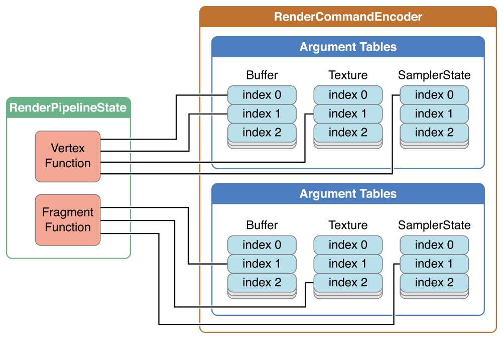
The MTLRenderCommandEncoder methods discussed in this section specify resources that are used as arguments for the vertex and fragment shader functions, which are specified by the vertexFunction and fragmentFunction properties in a MTLRenderPipelineState object. These methods assign a shader resource (buffers, textures, and samplers) to the corresponding argument table index (atIndex) in the render command encoder, as shown in Figure 5-3.
The following setVertex* methods assign one or more resources to corresponding arguments of a vertex shader function.
These setFragment* methods similarly assign one or more resources to corresponding arguments of a fragment shader function.
There are a maximum of 31 entries in the buffer argument table, 31 entries in the texture argument table, and 16 entries in the sampler state argument table.
The attribute qualifiers that specify resource locations in the Metal shading language source code must match the argument table indices in the Metal framework methods. In Listing 5-7, two buffers (posBuf and texCoordBuf) with indices 0 and 1, respectively, are defined for the vertex shader.
Listing 5-7 Metal Framework: Specifying Resources for a Vertex Function
[renderEnc setVertexBuffer:posBuf offset:0 atIndex:0]; |
[renderEnc setVertexBuffer:texCoordBuf offset:0 atIndex:1]; |
In Listing 5-8, the function signature has corresponding arguments with the attribute qualifiers buffer(0) and buffer(1).
Listing 5-8 Metal Shading Language: Vertex Function Arguments Match the Framework Argument Table Indices
vertex VertexOutput metal_vert(float4 *posData [[ buffer(0) ]], |
float2 *texCoordData [[ buffer(1) ]]) |
Similarly, in Listing 5-9, a buffer, a texture, and a sampler (fragmentColorBuf, shadeTex, and sampler, respectively), all with index 0, are defined for the fragment shader.
Listing 5-9 Metal Framework: Specifying Resources for a Fragment Function
[renderEnc setFragmentBuffer:fragmentColorBuf offset:0 atIndex:0]; |
[renderEnc setFragmentTexture:shadeTex atIndex:0]; |
[renderEnc setFragmentSamplerState:sampler atIndex:0]; |
In Listing 5-10, the function signature has corresponding arguments with the attribute qualifiers buffer(0), texture(0), and sampler(0), respectively.
Listing 5-10 Metal Shading Language: Fragment Function Arguments Match the Framework Argument Table Indices
fragment float4 metal_frag(VertexOutput in [[stage_in]],
                           float4 *fragColorData [[ buffer(0) ]],
                           texture2d<float> shadeTexValues [[ texture(0) ]],
sampler samplerValues [[ sampler(0) ]] ) |
Vertex Descriptor for Data Organization
In Metal framework code, there can be one MTLVertexDescriptor for every pipeline state that describes the organization of data input to the vertex shader function and shares resource location information between the shading language and framework code.
In Metal shading language code, per-vertex inputs (such as scalars or vectors of integer or floating-point values) can be organized in one struct, which can be passed in one argument that is declared with the [[ stage_in ]] attribute qualifier, as seen in the VertexInput struct for the example vertex function vertexMath in Listing 5-11. Each field of the per-vertex input struct has the [[ attribute(index) ]] qualifier, which specifies the index in the vertex attribute argument table.
Listing 5-11 Metal Shading Language: Vertex Function Inputs with Attribute Indices
struct VertexInput {
    float2    position [[ attribute(0) ]];
    float4    color    [[ attribute(1) ]];
    float2    uv1      [[ attribute(2) ]];
    float2    uv2      [[ attribute(3) ]];
};

struct VertexOutput {
    float4 pos [[ position ]];
    float4 color;
};

vertex VertexOutput vertexMath(VertexInput in [[ stage_in ]])
{
  VertexOutput out;
  out.pos = float4(in.position.x, in.position.y, 0.0, 1.0);

  float sum1 = in.uv1.x + in.uv2.x;
  float sum2 = in.uv1.y + in.uv2.y;
  out.color = in.color + float4(sum1, sum2, 0.0f, 0.0f);
  return out;
} |
To refer to the shader function input using the [[ stage_in ]] qualifier, describe a MTLVertexDescriptor object and then set it as the vertexDescriptor property of MTLRenderPipelineState. MTLVertexDescriptor has two properties: attributes and layouts.
The attributes property of MTLVertexDescriptor is a MTLVertexAttributeDescriptorArray object that defines how each vertex attribute is organized in a buffer that is mapped to a vertex function argument. The attributes property can support access to multiple attributes (such as vertex coordinates, surface normals, and texture coordinates) that are interleaved within the same buffer. The order of the members in the shading language code does not have to be preserved in the buffer in the framework code. Each vertex attribute descriptor in the array has the following properties that provide a vertex shader function information to locate and load the argument data:
bufferIndex, which is an index to the buffer argument table that specifies whichMTLBufferis accessed. The buffer argument table is discussed in Specifying Resources for a Render Command Encoder.format, which specifies how the data should be interpreted in the framework code. If the data type is not an exact type match, it may be converted or expanded. For example, if the shading language type ishalf4and the frameworkformatisMTLVertexFormatFloat2, then when the data is used as an argument to the vertex function, it may be converted from float to half and expanded from two to four elements (with 0.0, 1.0 in the last two elements).offset, which specifies where the data can be found from the start of a vertex.
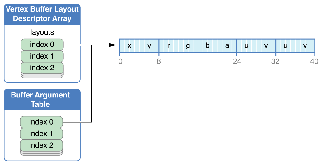
Figure 5-4 illustrates a MTLVertexAttributeDescriptorArray in Metal framework code that implements an interleaved buffer that corresponds to the input to the vertex function vertexMath in the shading language code in Listing 5-11.
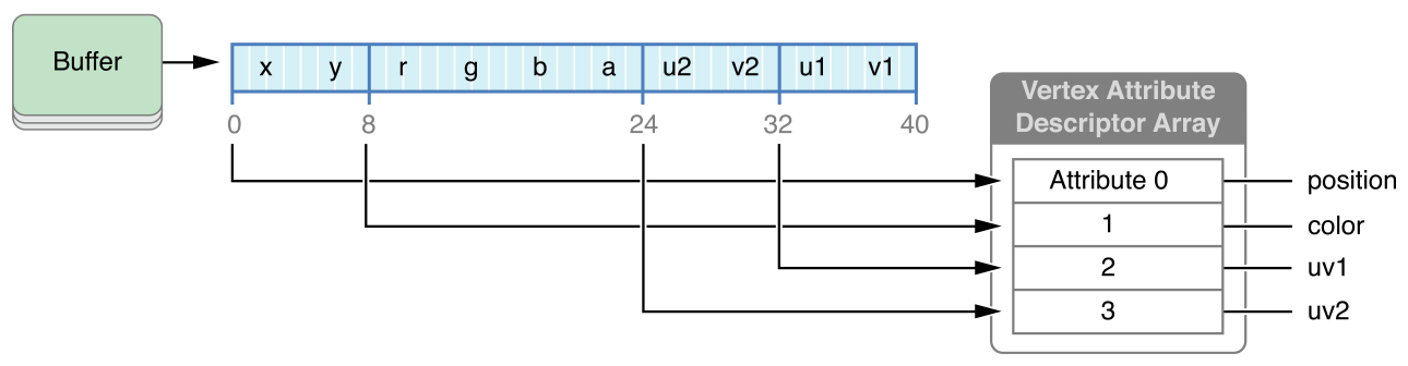
Listing 5-12 shows the Metal framework code that corresponds to the interleaved buffer shown in Figure 5-4.
Listing 5-12 Metal Framework: Using a Vertex Descriptor to Access Interleaved Data
id <MTLFunction> vertexFunc = [library newFunctionWithName:@"vertexMath"];
MTLRenderPipelineDescriptor* pipelineDesc =
                             [[MTLRenderPipelineDescriptor alloc] init];
MTLVertexDescriptor* vertexDesc = [[MTLVertexDescriptor alloc] init];

vertexDesc.attributes[0].format = MTLVertexFormatFloat2;
vertexDesc.attributes[0].bufferIndex = 0;
vertexDesc.attributes[0].offset = 0;
vertexDesc.attributes[1].format = MTLVertexFormatFloat4;
vertexDesc.attributes[1].bufferIndex = 0;
vertexDesc.attributes[1].offset = 2 * sizeof(float);  // 8 bytes
vertexDesc.attributes[2].format = MTLVertexFormatFloat2;
vertexDesc.attributes[2].bufferIndex = 0;
vertexDesc.attributes[2].offset = 8 * sizeof(float);  // 32 bytes
vertexDesc.attributes[3].format = MTLVertexFormatFloat2;
vertexDesc.attributes[3].bufferIndex = 0;
vertexDesc.attributes[3].offset = 6 * sizeof(float);  // 24 bytes
vertexDesc.layouts[0].stride = 10 * sizeof(float);    // 40 bytes
vertexDesc.layouts[0].stepFunction = MTLVertexStepFunctionPerVertex;

pipelineDesc.vertexDescriptor = vertexDesc;
pipelineDesc.vertexFunction = vertFunc; |
Each MTLVertexAttributeDescriptor object in the attributes array of the MTLVertexDescriptor object corresponds to the indexed struct member in VertexInput in the shader function. attributes[1].bufferIndex = 0 specifies the use of the buffer at index 0 in the argument table. (In this example, each MTLVertexAttributeDescriptor has the same bufferIndex, so each refers to the same vertex buffer at index 0 in the argument table.) The offset values specify the location of data within the vertex, so attributes[1].offset = 2 * sizeof(float) locates the start of the corresponding data 8 bytes from the start of the buffer. The format values are chosen to match the data type in the shader function, so attributes[1].format = MTLVertexFormatFloat4 specifies the use of four floating-point values.
The layouts property of MTLVertexDescriptor is a MTLVertexBufferLayoutDescriptorArray. For each MTLVertexBufferLayoutDescriptor in layouts, the properties specify how vertex and attribute data are fetched from the corresponding MTLBuffer in the argument table when Metal draws primitives. (For more on drawing primitives, see Drawing Geometric Primitives.) The stepFunction property of MTLVertexBufferLayoutDescriptor determines whether to fetch attribute data for every vertex, for some number of instances, or just once. If stepFunction is set to fetch attribute data for some number of instances, then the stepRate property of MTLVertexBufferLayoutDescriptor determines how many instances. The stride property specifies the distance between the data of two vertices, in bytes.
Figure 5-5 depicts the MTLVertexBufferLayoutDescriptor that corresponds to the code in Listing 5-12. layouts[0] specifies how vertex data is fetched from corresponding index 0 in the buffer argument table. layouts[0].stride specifies a distance of 40 bytes between the data of two vertices. The value of layouts[0].stepFunction, MTLVertexStepFunctionPerVertex, specifies that attribute data is fetched for every vertex when drawing. If the value of stepFunction is MTLVertexStepFunctionPerInstance, the stepRate property determines how often attribute data is fetched. For example, if stepRate is 1, data is fetched for every instance; if stepRate is 2, for every two instances, and so on.
Performing Fixed-Function Render Command Encoder Operations
Use these MTLRenderCommandEncoder methods to set fixed-function graphics state values:
setViewport:specifies the region, in screen coordinates, which is the destination for the projection of the virtual 3D world. The viewport is 3D, so it includes depth values; for details, see Working with Viewport and Pixel Coordinate Systems.setTriangleFillMode:determines whether to rasterize triangle and triangle strip primitives with lines (MTLTriangleFillModeLines) or as filled triangles (MTLTriangleFillModeFill). The default value isMTLTriangleFillModeFill.setCullMode:andsetFrontFacingWinding:are used together to determine if and how culling is applied. You can use culling for hidden surface removal on some geometric models, such as an orientable sphere rendered with filled triangles. (A surface is orientable if its primitives are consistently drawn in either clockwise or counterclockwise order.)The value of
setFrontFacingWinding:indicates whether a front-facing primitive has its vertices drawn in clockwise (MTLWindingClockwise) or counterclockwise (MTLWindingCounterClockwise) order. The default value isMTLWindingClockwise.The value of
setCullMode:determines whether to perform culling (MTLCullModeNone, if culling disabled) or which type of primitive to cull (MTLCullModeFrontorMTLCullModeBack).
Use the following MTLRenderCommandEncoder methods to encode fixed-function state change commands:
setScissorRect:specifies a 2D scissor rectangle. Fragments that lie outside the specified scissor rectangle are discarded.setDepthStencilState:sets the depth and stencil test state as described in Depth and Stencil States.setStencilReferenceValue:specifies the stencil reference value.setDepthBias:slopeScale:clamp:specifies an adjustment for comparing shadow maps to the depth values output from fragment shaders.setVisibilityResultMode:offset:determines whether to monitor if any samples pass the depth and stencil tests. If set toMTLVisibilityResultModeBoolean, then if any samples pass the depth and stencil tests, a non-zero value is written to a buffer specified by thevisibilityResultBufferproperty ofMTLRenderPassDescriptor, as described in Creating a Render Pass Descriptor.You can use this mode to perform occlusion testing. If you draw a bounding box and no samples pass, then you may conclude that any objects within that bounding box are occluded and thus do not require rendering.
setBlendColorRed:green:blue:alpha:specifies the constant blend color and alpha values, as detailed in Configuring Blending in a Render Pipeline Attachment Descriptor.
Working with Viewport and Pixel Coordinate Systems
Metal defines its Normalized Device Coordinate (NDC) system as a 2x2x1 cube with its center at (0, 0, 0.5). The left and bottom for x and y, respectively, of the NDC system are specified as -1. The right and top for x and y, respectively, of the NDC system are specified as +1.
The viewport specifies the transformation from NDC to the window coordinates. The Metal viewport is a 3D transformation specified by the setViewport: method of MTLRenderCommandEncoder. The origin of the window coordinates is in the upper-left corner.
In Metal, pixel centers are offset by (0.5, 0.5). For example, the pixel at the origin has its center at (0.5, 0.5); the center of the adjacent pixel to its right is (1.5, 0.5). This is also true for textures.
Performing Depth and Stencil Operations
The depth and stencil operations are fragment operations that you specify as follows:
Specify a custom
MTLDepthStencilDescriptorobject that contains settings for the depth/stencil state. Creating a customMTLDepthStencilDescriptorobject may require creating one or twoMTLStencilDescriptorobjects that are applicable to front-facing primitives and back-facing primitives.Create a
MTLDepthStencilStateobject by calling thenewDepthStencilStateWithDescriptor:method ofMTLDevicewith a depth/stencil state descriptor.To set the depth/stencil state, call the
setDepthStencilState:method ofMTLRenderCommandEncoderwith theMTLDepthStencilState.If the stencil test is in use, call
setStencilReferenceValue:to specify the stencil reference value.
If the depth test is enabled, the render pipeline state must include a depth attachment to support writing the depth value. To perform the stencil test, the render pipeline state must include a stencil attachment. To configure attachments, see Creating and Configuring a Render Pipeline Descriptor.
If you will be changing the depth/stencil state regularly, then you may want to reuse the state descriptor object, modifying its property values as needed to create more state objects.
Use the properties of a MTLDepthStencilDescriptor object as follows to set the depth and stencil state:
To enable writing the depth value to the depth attachment, set
depthWriteEnabledtoYES.depthCompareFunctionspecifies how the depth test is performed. If a fragment’s depth value fails the depth test, the fragment is discarded. For example, the commonly usedMTLCompareFunctionLessfunction causes fragment values that are further away from the viewer than the (previously written) pixel depth value to fail the depth test; that is, the fragment is considered occluded by the earlier depth value.The
frontFaceStencilandbackFaceStencilproperties each specify a separateMTLStencilDescriptorobject for front- and back-facing primitives. To use the same stencil state for both front- and back-facing primitives, you can assign the sameMTLStencilDescriptorto bothfrontFaceStencilandbackFaceStencilproperties. To explicitly disable the stencil test for one or both faces, set the corresponding property tonil, the default value.
Explicit disabling of a stencil state is not necessary. Metal determines whether to enable a stencil test based on whether the stencil descriptor is configured for a valid stencil operation.
Listing 5-13 shows an example of creation and use of a MTLDepthStencilDescriptor object for the creation of a MTLDepthStencilState object, which is then used with a render command encoder. In this example, the stencil state for the front-facing primitives is accessed from the frontFaceStencil property of the depth/stencil state descriptor. The stencil test is explicitly disabled for the back-facing primitives.
Listing 5-13 Creating and Using a Depth/Stencil Descriptor
MTLDepthStencilDescriptor *dsDesc = [[MTLDepthStencilDescriptor alloc] init]; |
if (dsDesc == nil) |
exit(1); // if the descriptor could not be allocated |
dsDesc.depthCompareFunction = MTLCompareFunctionLess; |
dsDesc.depthWriteEnabled = YES; |
dsDesc.frontFaceStencil.stencilCompareFunction = MTLCompareFunctionEqual; |
dsDesc.frontFaceStencil.stencilFailureOperation = MTLStencilOperationKeep; |
dsDesc.frontFaceStencil.depthFailureOperation = MTLStencilOperationIncrementClamp; |
dsDesc.frontFaceStencil.depthStencilPassOperation = |
MTLStencilOperationIncrementClamp; |
dsDesc.frontFaceStencil.readMask = 0x1; |
dsDesc.frontFaceStencil.writeMask = 0x1; |
dsDesc.backFaceStencil = nil; |
id <MTLDepthStencilState> dsState = [device |
newDepthStencilStateWithDescriptor:dsDesc]; |
[renderEnc setDepthStencilState:dsState]; |
[renderEnc setStencilReferenceValue:0xFF]; |
The following properties define a stencil test in the MTLStencilDescriptor:
readMaskis a bitmask; the GPU computes the bitwise AND of this mask with both the stencil reference value and the stored stencil value. The stencil test is a comparison between the resulting masked reference value and the masked stored value.writeMaskis a bitmask that restricts which stencil values are written to the stencil attachment by the stencil operations.stencilCompareFunctionspecifies how the stencil test is performed for fragments. In Listing 5-13, the stencil comparison function isMTLCompareFunctionEqual, so the stencil test passes if the masked reference value is equal to masked stencil value already stored at the location of a fragment.stencilFailureOperation,depthFailureOperation, anddepthStencilPassOperationspecify what to do to a stencil value stored in the stencil attachment for three different test outcomes: if the stencil test fails, if the stencil test passes and the depth test fails, or if both stencil and depth tests succeed, respectively. In the preceding example, the stencil value is unchanged (MTLStencilOperationKeep) if the stencil test fails, but it is incremented if the stencil test passes, unless the stencil value is already the maximum possible (MTLStencilOperationIncrementClamp).
Drawing Geometric Primitives
After you have established the pipeline state and fixed-function state, you can call the following MTLRenderCommandEncoder methods to draw the geometric primitives. These draw methods reference resources (such as buffers that contain vertex coordinates, texture coordinates, surface normals, and other data) to execute the pipeline with the shader functions and other state you have previously established with MTLRenderCommandEncoder.
drawPrimitives:vertexStart:vertexCount:instanceCount:renders a number of instances (instanceCount) of primitives using vertex data in contiguous array elements, starting with the first vertex at the array element at the indexvertexStartand ending at the array element at the indexvertexStart + vertexCount - 1.drawPrimitives:vertexStart:vertexCount:is the same as the previous method with aninstanceCountof 1.drawIndexedPrimitives:indexCount:indexType:indexBuffer:indexBufferOffset:instanceCount:renders a number of instances (instanceCount) of primitives using an index list specified in theMTLBufferobjectindexBuffer.indexCountdetermines the number of indices. The index list starts at the index that isindexBufferOffsetbyte offset within the data inindexBuffer.indexBufferOffsetmust be a multiple of the size of an index, which is determined byindexType.drawIndexedPrimitives:indexCount:indexType:indexBuffer:indexBufferOffset:is similar to the previous method with aninstanceCountof 1.
For every primitive rendering method listed above, the first input value determines the primitive type with one of the MTLPrimitiveType values. The other input values determine which vertices are used to assemble the primitives. For all these methods, the instanceStart input value determines the first instance to draw, and instanceCount input value determines how many instances to draw.
As previously discussed, setTriangleFillMode: determines whether the triangles are rendered as filled or wireframe, and the setCullMode: and setFrontFacingWinding: settings determine whether the GPU culls triangles during rendering. For more information, see Fixed-Function State Operations).
When rendering a point primitive, the shader language code for the vertex function must provide the [[ point_size ]] attribute, or the point size is undefined.
When rendering a triangle primitive with flat shading, the attributes of the first vertex (also known as the provoking vertex) are used for the whole triangle. The shader language code for the vertex function must provide the [[ flat ]] interpolation qualifier.
For details on all Metal shading language attributes and qualifiers, see Metal Shading Language Guide.
Ending a Rendering Pass
To terminate a rendering pass, call endEncoding on the render command encoder. After ending the previous command encoder, you can create a new command encoder of any type to encode additional commands into the command buffer.
Code Example: Drawing a Triangle
The following steps, illustrated in Listing 5-14, describe a basic procedure for rendering a triangle.
Create a
MTLCommandQueueand use it to create aMTLCommandBuffer.Create a
MTLRenderPassDescriptorthat specifies a collection of attachments that serve as the destination for encoded rendering commands in the command buffer.In this example, only the first color attachment is set up and used. (The variable
currentTextureis assumed to contain aMTLTexturethat is used for a color attachment.) Then theMTLRenderPassDescriptoris used to create a newMTLRenderCommandEncoder.Create two
MTLBufferobjects,posBufandcolBuf, and callnewBufferWithBytes:length:options:to copy vertex coordinate and vertex color data,posDataandcolData, respectively, into the buffer storage.Call the
setVertexBuffer:offset:atIndex:method ofMTLRenderCommandEncodertwice to specify the coordinates and colors.The
atIndexinput value of thesetVertexBuffer:offset:atIndex:method corresponds to the attributebuffer(atIndex)in the source code of the vertex function.Create a
MTLRenderPipelineDescriptorand establish the vertex and fragment functions in the pipeline descriptor:Create a
MTLLibrarywith source code fromprogSrc, which is assumed to be a string that contains Metal shader source code.Then call the
newFunctionWithName:method ofMTLLibraryto create theMTLFunctionvertFuncthat represents the function calledhello_vertexand to create theMTLFunctionfragFuncthat represents the function calledhello_fragment.Finally, set the
vertexFunctionandfragmentFunctionproperties of theMTLRenderPipelineDescriptorwith theseMTLFunctionobjects.
Create a
MTLRenderPipelineStatefrom theMTLRenderPipelineDescriptorby callingnewRenderPipelineStateWithDescriptor:error:or a similar method ofMTLDevice. Then thesetRenderPipelineState:method ofMTLRenderCommandEncoderuses the created pipeline state for rendering.Call the
drawPrimitives:vertexStart:vertexCount:method ofMTLRenderCommandEncoderto append commands to perform the rendering of a filled triangle (typeMTLPrimitiveTypeTriangle).Call the
endEncodingmethod to end encoding for this rendering pass. And call thecommitmethod ofMTLCommandBufferto execute the commands on the device.
Listing 5-14 Metal Code for Drawing a Triangle
id <MTLDevice> device = MTLCreateSystemDefaultDevice(); |
id <MTLCommandQueue> commandQueue = [device newCommandQueue]; |
id <MTLCommandBuffer> commandBuffer = [commandQueue commandBuffer]; |
MTLRenderPassDescriptor *renderPassDesc |
= [MTLRenderPassDescriptor renderPassDescriptor]; |
renderPassDesc.colorAttachments[0].texture = currentTexture; |
renderPassDesc.colorAttachments[0].loadAction = MTLLoadActionClear; |
renderPassDesc.colorAttachments[0].clearColor = MTLClearColorMake(0.0,1.0,1.0,1.0); |
id <MTLRenderCommandEncoder> renderEncoder = |
[commandBuffer renderCommandEncoderWithDescriptor:renderPassDesc]; |
static const float posData[] = { |
0.0f, 0.33f, 0.0f, 1.f, |
-0.33f, -0.33f, 0.0f, 1.f, |
0.33f, -0.33f, 0.0f, 1.f, |
}; |
static const float colData[] = { |
1.f, 0.f, 0.f, 1.f, |
0.f, 1.f, 0.f, 1.f, |
0.f, 0.f, 1.f, 1.f, |
}; |
id <MTLBuffer> posBuf = [device newBufferWithBytes:posData |
length:sizeof(posData) options:nil]; |
id <MTLBuffer> colBuf = [device newBufferWithBytes:colorData |
length:sizeof(colData) options:nil]; |
[renderEncoder setVertexBuffer:posBuf offset:0 atIndex:0]; |
[renderEncoder setVertexBuffer:colBuf offset:0 atIndex:1]; |
NSError *errors; |
id <MTLLibrary> library = [device newLibraryWithSource:progSrc options:nil |
error:&errors]; |
id <MTLFunction> vertFunc = [library newFunctionWithName:@"hello_vertex"]; |
id <MTLFunction> fragFunc = [library newFunctionWithName:@"hello_fragment"]; |
MTLRenderPipelineDescriptor *renderPipelineDesc |
= [[MTLRenderPipelineDescriptor alloc] init]; |
renderPipelineDesc.vertexFunction = vertFunc; |
renderPipelineDesc.fragmentFunction = fragFunc; |
renderPipelineDesc.colorAttachments[0].pixelFormat = currentTexture.pixelFormat; |
id <MTLRenderPipelineState> pipeline = [device |
newRenderPipelineStateWithDescriptor:renderPipelineDesc error:&errors]; |
[renderEncoder setRenderPipelineState:pipeline]; |
[renderEncoder drawPrimitives:MTLPrimitiveTypeTriangle |
vertexStart:0 vertexCount:3]; |
[renderEncoder endEncoding]; |
[commandBuffer commit]; |
In Listing 5-14, a MTLFunction object represents the shader function called hello_vertex. The setVertexBuffer:offset:atIndex: method of MTLRenderCommandEncoder is used to specify the vertex resources (in this case, two buffer objects) that are passed as arguments into hello_vertex. The atIndex input value of the setVertexBuffer:offset:atIndex: method corresponds to the attribute buffer(atIndex) in the source code of the vertex function, as shown in Listing 5-15.
Listing 5-15 Corresponding Shader Function Declaration
vertex VertexOutput hello_vertex( |
const global float4 *pos_data [[ buffer(0) ]], |
const global float4 *color_data [[ buffer(1) ]]) |
{ |
... |
} |
Encoding a Single Rendering Pass Using Multiple Threads
In some cases, your app’s performance can be limited by the single-CPU workload of encoding commands for a single rendering pass. However, attempting to circumvent this bottleneck by separating the workload into multiple rendering passes encoded on multiple CPU threads can also adversely impact performance, because each rendering pass requires its own intermediate attachment store and load actions to preserve the render target contents.
Instead, use a MTLParallelRenderCommandEncoder object, which manages multiple subordinate MTLRenderCommandEncoder objects that share the same command buffer and render pass descriptor. The parallel render command encoder ensures that the attachment load and store actions occur only at the start and end of the entire rendering pass, not at the start and end of each subordinate render command encoder’s set of commands. With this architecture, you can assign each MTLRenderCommandEncoder object to its own thread in parallel in a safe and highly performant manner.
To create a parallel render command encoder, use the parallelRenderCommandEncoderWithDescriptor: method of a MTLCommandBuffer object. To create subordinate render command encoders, call the renderCommandEncoder method of the MTLParallelRenderCommandEncoder object once for each CPU thread from which you want to perform command encoding. All subordinate command encoders created from the same parallel render command encoder encode commands to the same command buffer. Commands are encoded to a command buffer in the order in which the render command encoders are created. To end encoding for a specific render command encoder, call the endEncoding method of MTLRenderCommandEncoder. After you have ended encoding on all render command encoders created by the parallel render command encoder, call the endEncoding method of MTLParallelRenderCommandEncoder to end the rendering pass.
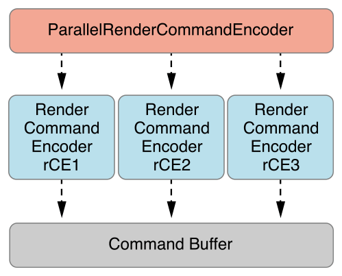
Listing 5-16 shows the MTLParallelRenderCommandEncoder creating three MTLRenderCommandEncoder objects: rCE1, rCE2, and rCE3.
Listing 5-16 A Parallel Rendering Encoder with Three Render Command Encoders
MTLRenderPassDescriptor *renderPassDesc
                     = [MTLRenderPassDescriptor renderPassDescriptor];
renderPassDesc.colorAttachments[0].texture = currentTexture;
renderPassDesc.colorAttachments[0].loadAction = MTLLoadActionClear;
renderPassDesc.colorAttachments[0].clearColor = MTLClearColorMake(0.0,0.0,0.0,1.0);

id <MTLParallelRenderCommandEncoder> parallelRCE = [commandBuffer
                     parallelRenderCommandEncoderWithDescriptor:renderPassDesc];
id <MTLRenderCommandEncoder> rCE1 = [parallelRCE renderCommandEncoder];
id <MTLRenderCommandEncoder> rCE2 = [parallelRCE renderCommandEncoder];
id <MTLRenderCommandEncoder> rCE3 = [parallelRCE renderCommandEncoder];

//  not shown: rCE1, rCE2, and rCE3 call methods to encode graphics commands
//
//  rCE1 commands are processed first, because it was created first
//  even though rCE2 and rCE3 end earlier than rCE1
[rCE2 endEncoding];
[rCE3 endEncoding];
[rCE1 endEncoding];

//  all MTLRenderCommandEncoders must end before MTLParallelRenderCommandEncoder
[parallelRCE endEncoding]; |
The order in which the command encoders call endEncoding is not relevant to the order in which commands are encoded and appended to the MTLCommandBuffer. For MTLParallelRenderCommandEncoder, the MTLCommandBuffer always contains commands in the order that the subordinate render command encoders were created, as seen in Figure 5-6.
Copyright © 2016 Apple Inc. All Rights Reserved. Terms of Use | Privacy Policy | Updated: 2016-12-12